


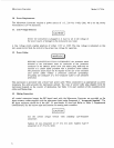
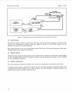

Microwave Converter Model
11793A
FREPUENCY
OUTPUT
OFFSET TTL
0
I
:::::
D00000
0000
0
0
0000
00
0
0000
0
0
0
000000
00000
Q
HP
6902A
MEASURING RECEIVER
SI
II
FREOUENCY
I
OFFSET MODE RF
INPUT INPUT
I
OR
1
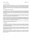
Figure
3.
Microwave Convertor Interconnections and Typical Test Setup
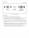
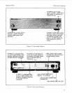
21.
Panel Features
Front-panel features consist of the
LO
input, RF input, and the IF output connectors. For Options
020
and
021,
the connectors are located on the rear panel. See Figure
4,
Front-Panel Features
for the
standard locations of front-panel connectors.
Rear-panel features are the Line Voltage Select Switch, Fuse, Power Cord and the Frequency Offset input
connectors. See Figure
5,
Rear -Panel Features.
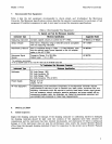
22.
Operator Checks
Operator’s checks consist of insuring that a fuse of proper value is installed, that the power cord is plugged
in, that the signal/control lines are connected, and that both the measuring instrument and the external
LO
are connected and turned on.
23.
Operator Maintenance
The only maintenance needed by the Microwave Converter is replacement of the primary power fuse.
To replace the fuse, insert a standard screwdriver into the fuseholder and push in against the spring. Turn
counterclockwise (while pushing with a slight pressure) until the fuseholder is released. Remove and
replace the fuse with
a
new fuse of identical value.
10