


Microwave Converter Model
1
1793A
RF
Devices (Service Sheets
1
and
2)
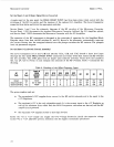
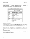
Because of the diversity
of
test equipment and techniques available
for
troubleshooting the
high-frequency devices, no specific procedures are given. Check the performance parameters of the
RF
devices against the following table, Table
10.
Also check connectors and cables.
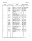
Table
10.
Performance Parameters
Device
AT1
3 dB
Attenuator
FL1
Low-Pass
Filter
s1,
s2
Switch
u1
LO
Amplifier
Performance Parameters
to
Check
Attenuation:
2.5
to 3.5 dB at 18
GHz
2.0
to
4.0
dB at
26.5
GHz
SWR:
4.251
at
26.5
GHz
~~ ~~
3 dB Corner:
900
to
1100
MHz
Passband Insertion
Loss:
<0.25
dB at
800
MHz
Insertion Loss:
4.5
dB at
26.5
GHz
SWR:
<2.0:1
at
26.5
GHz
Frequency Range:
18
to
26.5
GHz
Gain:
>11
dB
SWR:
C2.51
u2
IF
Amplifier
u3
Mixer
Frequency Range:
10
to
700
MHz
Gain: 14 dB
SWR:
<1.8:1
LO Frequency Range:
2
to
26.5
GHz
RF
Frequency Range: 1.3 to
26.5
GHz
LO Power:
>+8
dBm
Conversion Loss:
<lo
dB
SWR:
<4:1
Control Devices (Service Sheet
3)
Set a power supply to
0
Vdc and connect it to the FREQ OFFSET INPUT connector. Set the supply to
0,
+3,
and
+S
Vdc respectively, and compare the logic levels
of
the logic devices with those listed in Table
9.
When specifically checking the drive transistors 42, Q3,Q4, or QS, note the following:
The switch solenoids automatically disconnect after completion of switching. Therefore,
it
is difficult to
distinguish between a drive transistor that
is
on but not drawing current, or one that is off and not
drawing current. The collector voltages will differ by only a few
mV.
If any of the transistors are known
to be working, compare the on and
off
voltages of the suspected transistor against those of a known
good
one.
Power Supplies (Service Sheet
3)
Check the points indicated in the schematic diagram for dc level and ac ripple. Note that the
+SV
Regulator is dependent on the
+
12V Regulator.
26