


Microwave Converter Model
1
1793A
Level
at
INPUT
RF
LO
FREQ
U1A U1B U3A
U3B
Path
Amp
OFFSET
Pin
1
Pin
6
Pin 3
Pin
6
Direct out
<2.0v
H
L
H H
Down-Convert In
2.0 to
3.w
H
H
L L
Down-Convert
Out
>3.av
L
H
H
L
Service Sheets
1
and
2
(Input Signal Down-Converter)
U3C
Q2
Q3
Q4
Q5
Pin
8
L
Off
Off On On
H On On
Off
Off
L
Off
On
Off
On
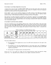
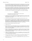
A single input on the rear panel: the FREQ OFFSET INPUT, has three logic states which control both the
switching of the RF two paths, and the insertion of the optional LO Amplifier. The Level Comparator
senses the three states and drives the appropriate switches.
Service Sheets
1
and
2
are the schematic diagrams of the RF circuitry of the Microwave Converter.
Service Sheet
1
(SS
1)
documents the standard Microwave Converter (without the LO Amplifier option),
and Service Sheet 2 (SS2) documents the Microwave Converter with the LO Amplifier.
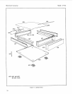
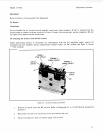
The operation of the RF components
is
discussed in the principles of operation for the Simplified Block
Diagram above. Note that the RF switches
(SI
and S2), shown in the schematic, automatically interrupt
the current flowing into the energized solenoid once the plunger switches the RF contacts. The plungers
latch via permanent magnets.
Service Sheet
3
(AI Switch
Control
Assembly)
The Level Comparator (UIA and U1B) and Decoder (U3A, U3B, and U3C) decode a three level input
(through the rear-panel FREQ OFFSET
INPUT
connector) into binary levels that control the
RF
switches
(see SS1 and SS2). The AND gates (U2) are simply open-collector inverters,'which drive the transistors
(42,
43,
44, QS) to switch on and energize the solenoids of the RF switches. Table
9
summarizes the
decoding
.
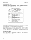
The power supplies used are:
m
The unregulated +26V supplies drive current to the RF switch solenoids, and
is
the input to the
+
12V Regulator.
8
The regulated
+
12V
is
the only adjustable supply. It
is
the current input to the
+SV
Regulator as
well as the reference from which both the Level comparator references are derived, and the RF
Amplifiers are powered.
e
The regulated +SV supplies current to most logic devices.
Either the
+26
or +12V supply can trigger the Over-Voltage Protection should the respective voltage
exceed +42 or
+
12V. LED DS
1
gives an indication that the supply is nominally operational.
24