


Model 11793A Microwave Converter
6.
Turn the instrument around
so
that the front of the instrument faces to the operator's left.
Desolder the 6, 5, 4, and
0
(blue, green, yellow, and black) wires from the A1 assembly.
7.
To
remove
T1
power transformer and its mounting bracket, unscrew the four screws located on
MP20 (mounting bracket). Separate transformer and the mounting bracket
by
removing the four
long screws passing through the transformer case.
8.
To remove the A1 assembly disconnect W12 (gray ribbon cable) at AlJl board connector,
unscrew the two screws at the VR3 heat sink, and turn the three board mounting stand-offs a
1/4 turn counterclockwise.
9.
To
remove MP 13 (main deck) and MP
14
(RF
module), remove the six Torxhead screws located on
the top and bottom of MPl (front frame). Remove the
six
screws connecting MP2 (side struts) to
MP13 (main deck). While supporting MP9, MPlO (front- and sub-panel) in one hand, carefully
slide MP13 (main deck) forward through the front frame opening just enough to reach the inside
cable connections.
Be careful that
you
do not bend the coax cables. Possible attenuation
or
interference
of
the
RF
signal may result.
a. When inside connections can be reached, use a
5/16 open-end wrench to disconnect the
semi-rigid coaxial cables from the front -panel connectors.
b. Carefully set aside the front panel and slide the main deck assembly out
of
the instrument
chassis.
To
remove the main deck on Options 020 and 021, disconnect the input cable connectors at the
back panel. Remove the main deck screws, then lift one side of the Main deck up until it clears
the side strut.
10.
To
remove MP14
(RF
module) from MP13 (main deck), remove the four screws that hold the
module to the main deck.
38.
Instrument
Assembly
Procedure
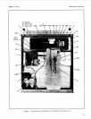
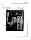
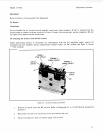
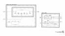
Note that Option 020 and 021 instruments differ from the standard and other option models in that the
main deck and transformer locations inside the instrument are reversed, when compared to the standard
and other option models as shown in Figures 7 and
8.
In Option
020
and 021 models, the RF module is in
the rear of the instrument), and the transformer is mounted in the front left corner.
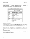
Use the correct torque wrench when installing
sub
-miniature
connectors.
Do
not exceed the following torque settings
for
this instrument:
1.5
N'm
for
the
3
mm
(T
IO)
screws,
2.0
N.m
for the
4
mm
(TIS)
screws.
29