


Microwave Converter Model 11793A
1.
2.
3.
4.
5.
6.
7.
8.
9.
10.
11.
12.
30
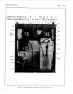
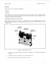
Place the RF Module upside down with the semi-rigid coax cables pointing to the left. Position
the main deck over the module with the four holes in the deck aligning with the four screw
holes in the module base. (The A1 assembly mounting stand-offs on MP13 (main deck) should be
upside down and on the opposite side of
MP
13 from the assembler.) Attach with four screws.
Take the main deck assembly (coax cables facing to the left) and slide into the main chassis
through the front frame (the two notches indicate the bottom edge and should be down). When
the coax cables are within two inches of the front frame edge, carefully connect the semi-rigid
coax cables to their respective front-panel connectors, using
a
S/16
inch open-end wrench.
For Option 020 and 021 instruments, main deck reassembly is just the opposite of disassembly.
Be careful that
you
do
not
bend the coax cables. Possible attenuation
or interference
of
the
RF
signal may result.
Carefully slide the main deck assembly into the instrument chassis until the front panel is within
the front frame and the mounting holes are aligned. Attach the front panel with the
six
Torxhead screws: 3 top,
3
bottom.
Attach the main deck assembly to the side struts using the
six
screws: three screws to a side.
Turn the instrument over. With the three A1 assembly mounting stand-offs on the main deck
(MP13) adjacent to the assembler, mount the A1 assembly to the main deck assembly. The three
large holes in the A1 assembly must align with the three mounting stand-offs, and the heat sink
holes must align with the deck mounting holes. Firmly seat the A1 assembly on the mounting
stand-offs and lock the stand-offs by turning the screw heads a
1/4
turn clockwise.
Fasten the transistor heat sink to the deck with two screws.
Connect W12 to AlJ1.
Mount transformer to the mounting bracket using the four long transformer screws. Mount the
bracket to the left side strut at the third and eighth holes (counting forward from the rear
frame) with four screws. Make sure that the transformer secondary wires (4,
5,
6)
face the corner
of
the A1 Switch Control Assembly.
Replace rear frame assembly to the side struts by connecting with four screws at the frame
corners. On instruments with serial number prefix 2407A, mount the rear panel to the rear
frame using eight screws. Ensure that the panel is aligned
so
that the electrical hardware is in
the same corner as the transformer.
Connect the black/green primary wire
(05)
on the transformer to the bottom right LINE
VOLTAGE lug (underneath the white/brown/gray wire
(9
1
81).
Connect the black primary wire
(0)
to the upper right LINE VOLTAGE lug.
Solder the colored secondary wires from the transformer to their respective solder pads on the
A1 Assembly: yellow to 4, green to
5:
and blue to
6.
Solder the black wire to the GND pad.
Reconnect
J8
(on
W
1
Sj
to the rear panel (in the
FREQ
OFFSET INPUT opening) using the
9/
16
inch lock washer and nut.