


Microwave Converter Model 11793A
12.
13.
14.
Remove
S2
from MP14 module base by removing the two corner screws.
Unsolder the three control wires
(1,
2,
5)
from S2.
Remove the Spira Shield (RF "EMI" gasket situated in the module base lip) only if damaged, or
replacement
of
MP14 module base.
40.
RF
Module Disassembly Procedure
for
Option
001,
011,
&
021
Instruments
1.
2.
3.
4.
5.
6.
7.
8.
9.
10.
11.
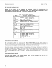
NOTE
When referring to switch ports: port
#I
is the far left (SMA)
connector, port
#2
is the second
SMA
connector, etc., when holding
the switch (label
up)
with the SMA connectors facing
you.
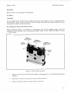
Disconnect W
1
2 (gray ribbon cable) at A 1
J
1.
Remove MP16 module cover by removing the 10 cover screws.
Disconnect cables W7 and W8 using
a
5/16
open-end wrench: W7 from
U3
mixer and FL1
Filter, W8 from
U2
IF Amp and S2 Switch, port #4.
Unsolder the orange and white/orange wires (3, 93) from U2. Unsolder the gray and
white/orange wires
(8,
9
3)
from
U
1.
Remove U2 and FL1 from MP16 by removing the two screws securing U2, then loosen the filter
clamp screw and slide the assembly
out.
Disconnect W9 from S1, port #1 and U1.
Disconnect the
LO
input semi-rigid coax cable (W4 in Option
001;
W14 in Option 01
1;
or
W18
in Option 021) from S1, port #2, being careful not to bend, crimp, or kink the cable. The radio
frequency interference
(RFI)
shielding grommet can be removed by slipping the grommet off of
the cable via the cable access slit.
Disconnect W6 from S1, port #3 and
U3.
Disconnect W5 from Sl, port #4 and U1 (power terminal side).
Unscrew the two Torxhead screws that secure the UlMP17 Amplifier mounting bracket to
MP
14 module base. The
U
1
amplifier and bracket can then be removed.
Unscrew the two Torxhead screws that secure the MP18 mixer mounting bracket to MP14
module base.
NOTE
Remember the order in which the stiffener bar and mixer bracket are
assembled. The stiffener bar and mixer bracket assembly
order
is
different between each brand
of
mixer used.
12.
Disconnect
U3
from the Attenuator (AT
1).
U3 Mixer and bracket can then be disassembled.
32