


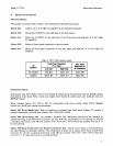
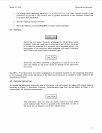

Model
11793A
Microwave Converter
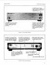
IF OUTPUT: The
IF
output,
Type-N connector, couples the IF
output signal into measuring in-
strument
RF
input.
LO INPUT: The LO input, 3.5 mm
connector, couples an external
oscillator signal source to the
instrument.
RF
INPUT: The RF input, 3.5mm
connector couples the microwave
input signal into the instrument.
The maximum allowable input
power is +30 dBm (lwatt), the
input impedance is
50 ohms
nominal.
Figure
4.
Front-Panel Features
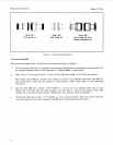
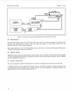
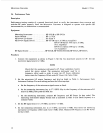
RF INPUT is a rear-panel input
for the
RF
signal (instead of the
standard front-panel connection)
for option
020,
021 instruments.
IF OUTPUT is a rear-panel out-
put for the
IF
signal (instead of
the standard front-panel connec-
tion) for the option 020, 021
instruments.
FREQ OFFSET INPUT enables
the measuring instrument to con-
trol the switching circuitry.
T
T
I
LINE VOLTAGE SELECTION
SWITCH:
11
5
or 230 Vac
LO INPUT is a rear-panel input
for the LO signal (instead of the
standard, front-panel connection)
for the option
020,
021
instruments.
LINE VOLTAGE POWER CORD
CONNECTION
-1
FUSE HOLDER AND
.75A
FUSE
Figure
5.
Rear -Panel Features
11