


Microwave Converter Model 11793A
4.
Insert the paper under one of the contacts, and while pressing gently on the contact, slide the
paper through.
Do
not allow the alcohol to run inside the switch assembly.
Do
not
allow the paper
to shred.
Do this several times and repeat for the other switch contact.
5.
Saturate the edge
of
another sheet of paper with a freon-type degreaser and repeat step
4.
6.
Remove any shreds of paper that may have lodged in the contacts.
7.
Reinstall the switch cover. Note the orientation of the feedthrough terminals on the cover with
respect to the switch contacts.
8.
Replace the switch according to Paragraphs
4
1 or 42, RF Module assembly procedures.
37.
Instrument Disassembly Procedure
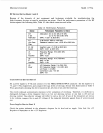
The 11793A Microwave Converter uses metric connecting hardware in the form of
3
mm (T10) and 4
mm (TlS) Torxhead screws (except for two small English thread Pozidriv screws mounting U1 to MP17).
Use the Torxhead size T 1
0
and T 1
5
bits that are provided, to disassemble and re-assemble the instrument.
The recommended torque wrench for use with the Torxhead bits
may
be
ordered as
HP
part number
8 7 3
0-00
12.
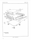
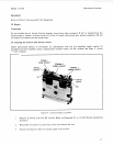
The major component blocks of the 11793A Microwave Converter are MP14 (RF Signal Processing
Module), A1 (A1 Switch Control Assembly), and T1 (Power Transformer). The
RF
module and the A1
assembly are mounted on MP13 (the Main Deck). The power transformer is mounted on MP2, the
instrument chassis left side strut. See Figures
6,
7,
and
8
to locate and identify parts and assemblies.
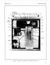
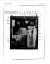
Note that Option 020 and 021 instruments differ from the standard and other option models
in
that the
main deck and transformer locations inside the instrument are reversed when compared to the standard
and other option models as shown in Figures 7 and
8.
In Option 020 and 021 models, the RF module
is
in
the rear of the instrument), and the transformer is mounted in the front left corner.
The following procedures allow the removal of the Microwave Converter components from within the
instrument chassis.
1.
Remove the top and bottom covers by loosening the screw in the middle of each cover rear edge.
These are captive screws and will cause the cover to push away from the front frame. Slide each
cover toward rear of the instrument to disengage, then lift up and away from the instrument.
2.
Remove the side covers in the same manner as that of the top and bottom covers.
3.
Remove the plastic trim from the top of the front frame by inserting a screwdriver into the rear
slots and gently prying up the strip.
4.
Disconnect
J8
on the rear panel by removing the
9/16
inch retaining nut and lock washer.
5.
Instruments with serial number prefix
2S20A have MP8 (back panel) riveted to MP3 (rear
frame). To remove the rear frame, unscrew the four corner screws that connect MP2 (side struts)
to MP3. Pull off the two wires
05
and
0
(black/green and black) on the LINE VOLTAGE switch
(both wires are
of
the quick disconnect type).
For instruments with serial number prefix 2407A, remove MP8 (back panel) from MP3 (rear
frame) by unscrewing eight screws. Pull off the two wires
OS
and
0
(black/green and black) on
the LINE VOLTAGE switch (both wires are of the quick disconnect type).
28