


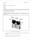

Model 11793A Microwave Converter
13.
Replace the side panels by centering each panel in the track formed by the side strut edges. Slide
the panel from the rear forward until the captive screw on the rear edge of the panel
is
in
contact with the rear frame. The screw should be in position to be tightened into the frame. The
panel will move forward into place as the screw is tightened.
14. Replace the top cover by placing the cover onto the upper frame of instrument, then slide cover
toward front of instrument. Tighten screw in middle of rear edge of cover while applying a
slight upward pressure on the leading edge (to keep the edge from jamming on front frame).
Guide cover into slot in the top of the front frame. Turn instrument over and repeat for the
bottom cover.
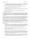
39.
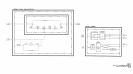
RF
Module Disassembly Procedure for Std, Option
010,
&
020
Instruments
1.
2.
3.
4.
5.
6.
7.
8.
9.
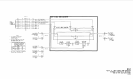
NOTE
When referring to switch ports: port
#I
is
the
far
left
(SMA)
connector, port
#2
is
the second
SMA
connector, etc., when holding
the switch (label
up)
with the
SMA
connectors facing
you.
Disconnect
W
I
2
(gray ribbon cable) at
A
1
J1.
Remove module cover (MP
16)
by removing the ten cover screws.
Disconnect cables
W7
and
W8
using a
5/16
open-end wrench:
W7
from U3 Mixer and FL1
Filter, W8 from U2 IF Amp and
S2
Switch, port #4.
Unsolder orange wire from
U2.
Remove
U2
and FL1 from MP16 by removing the two screws securing
U2,
then loosening the
filter clamp screw, and sliding the assembly out.
Disconnect the
LO
input semi-rigid coax cable
(W
1
in Standard instruments,
W
19
in Option
0
10
instruments, or W17 in Option
020
instruments) at U3, being careful not to bend, crimp, or kink
the cable. The radio frequency interference (RFI) shielding grommet can be removed by slipping
the grommet off of the cable via the cable access slit.
Repeat step
6
for
W2
(RF/IF Output) at
S2
port #3.
Repeat step
6
for W3 (RF Input) at
S2
port #2.
Unscrew the two Torxhead screws that secure the MP18 mixer mounting bracket to the MP14
module base.
NOTE
Remember the order in which the stiffener bar and mixer bracket are
assembled. The stiffener
bar
and
mixer bracket assembly order is
different between each brand of mixer used.
10. Disconnect
U3
Mixer from
AT1
Attenuator.
U3
Mixer and bracket can then be disassembled.
11. Disconnect
AT1
from S2.
31