


Model
11793A
Microwave Converter
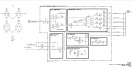
NOTE
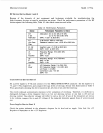
Mixer construction varies with manufacturer, and thus,
is
assembled
within the
RF
Module differently. For example, a Norsa2 mixer has a
stiffener bar placed between the mixer mounting bracket and the base
mounting castings. An
RHG
mixer has a stiffener bar placed above
the mixer mounting bracket.
10.
11.
12.
13.
14.
15.
16.
17.
18.
19.
2
0.
21.
22.
23.
2
4.
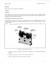
Attach the mixer assembly to the module base, but do not tighten the screws.
Tighten the connection to
AT1,
then tighten the mixer assembly screws.
Assemble
U1
HF LO
Amplifier and the
UlMP17
Mounting Bracket. Ensure that the
U1
power
terminal labels are up, and that the terminals face towards switch
S2.
Attach and secure
U
1
Amplifier assembly to
MP
1
4
module base.
Connect
W3
to
S2,
port
#2
(cable slots in module should be facing assembler). Insure that the
radio frequency interference
(RFI)
shielding grommet cradles the cable in the slot with the cable
access slit facing to the side.
Connect
W2
to
S2,
port
#3.
Ensure that the
RFI
Grommet
is
in place as described in step 11.
Connect
W
5
to the left port of
U1
Amplifier and to S1, port
#4.
Connect
W6
to the right port of
U3
mixer and to
S1,
port
#3.
Connect the
LO
input semi-rigid coax cable
(W4
in Option
001
instruments;
W
14
in Option
01
1
instruments; or
W18
in Option 021 instruments) to
S1,
port
#2.
Insure that the
RF
grommet
is
in
place as described in steps
11.
Connect
W9
to the right port of
U1
and to S1, port #l.
Attach
U2
to
MPl6
module cover.
Solder both the orange and white/orange wires
(3,
93)
to the
U2
amplifier terminal.
Place filter clamp around
FL1
and attach loosely to the cover.
Connect
FL
1
to
U2.
Tighten
FL
I
clamp.
Connect
W7
to
U3
and
FL1.
Connect
W
8
to
U2
and
S2,
port
#4.
Secure module cover to base. Snug the screws down finger tight, then tighten the screws,
working from the center out.
Connect
W12
to AlJ1.
35