


Microwave Converter Model
1
1793A
24.
Performance Tests
Description
Performance testing consists of a general functional check to verify the instrument down-converts and
switches RF paths properly. Since the Microwave Converter is designed to operate with specific HP
instrumentation, no substitution is recommended.
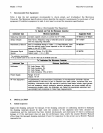
Equipment
Measuring Instrument
.................
HP 8901B or HP 8902A
Sensor Module
.........................
HP
1
1
7
9 2A
Microwave
LO
Source
.................
See Table
4
Microwave Signal Source
..............
HP 8673B (up to 26 GHz
Amplifier)
HP
8673B Option 008 (up to
26
GHz,
(w/o Amplifier)
HP 8672A Option
008
(up to 18 GHz,
w/o Amplifier)
RF
Signal Source
......................
HP 8642B, HP 8660C/86602B, HP 8662A,
HP
8663A
Procedure
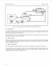
1.
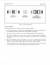
Connect the equipment as shown in Figure 3. Set the two microwave sources to
CW.
Set the
microwave signal source to
0
dBm.
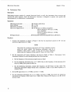
NOTE
Check that the measuring instrument's RF Power calibration factors
match the sensor module. The measuring instrument must be in
frequency offset mode in order to enter the
RF
Power calibration
factors into the Frequency Offset mode RF Power Cal Factor Table.
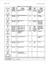
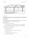
2.
Set the microwave
LO
source frequency and level as listed in Table
6.
Performance Tests
Znstrument Settings.
For each setting, perform the following steps:
a. Set the frequency of the microwave signal source as listed.
b.
On the measuring instrument, key in 27.3 SPCL. Key in the frequency of the microwave LO
source (in
MHz),
then press the MHz key.
c. On the measuring instrument, measure RF frequency and
RF
Power (in that order). The
measuring instrument's display should read as indicated in table
6.
(The listed frequency is a
nominal value.)
3.
Set the RF signal source
to
1270 MHz. and level
-
10 dBm.
4.
On the measuring instrument, key in 27.3 SPCL and enter
0
MHz. This leaves the measuring
instrument in frequency offset mode with
0
MHz offset. Measure RF Frequency and RF Power
(in that order).
12