


Model 11793A Microwave Converter
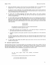
13. Disconnect
W2
from
S2,
port #3, being careful not to bend, crimp, or kink the cable.
14.
15.
Disconnect
W3
from
S2,
port
#2,
being careful not to bend, Lrimp, or kink the cable.
Disconnect AT1 from
S2,
port
#l.
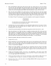
16.
Remove switches S1 and
S2
from MP14 module base by removing the two screws that secure
each switch.
Unsolder the control wires on each switch
(6,
4,
&
92
on
SI;
5,
1,
&
2
on
S2).
17.
18. Remove the Spira Shield
(RF
gasket situated in the module base lip) only
if
damaged, or
necessary for
MP
14
module base replacement.
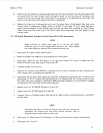
41.
RF
Module
Assembly
Procedure
for
Std, Option
010,
&
020
Instruments
1.
2.
3.
4.
5.
6.
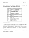
Spira Shield (RF gasket) replacement:
Spira Shield
is
inserted into a groove
in
the module base
(MP
14). Within the groove at spaced
intervals, are a series of rectangular protrusions called bosses. Insertion and seaming should begin
and finish at
a
boss.
a.
Use finger protection (such as a rubber finger protector) when working with the Spira Shield.
b.
Start at a boss on a straight section of the groove. Push the shielding into the groove using a
protected finger. Guide and twist the shielding to the next boss with the other hand.
c. At the next boss twist the shielding into a tight curl, guide it through the groove, then allow
the shielding to expand to hold itself in place.
d.
When an opening in the outer wall
of
the module
is
encountered, the shielding should be cut
diagonally. Begin the threading procedure on the other side of the opening.
e. Twist the shielding tighter when rounding corners.
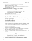
Solder the three control wires to the
S2
terminals
as
follows: green to
1,
brown to
2,
and red to
C(+).
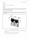
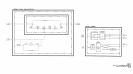
With the cable slots of the module facing towards the assembler, mount
S2
(label up and the
ports pointing to the center of the module) in the left hand side
of
the module base.
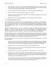
Connect AT
1
to port
#
1
of
S2.
Connect
U3
to the mixer bracket, ensuring that the mixer side port (which connects to the
IF
output) faces opposite to the bracket mounting holes.
Connect U3 to AT1, but do not tighten.
NOTE
Mixer construction varies with manufacturer, and thus, is assembled
within
the
RF
Module differently.
For
example, a Norsal mixer has a
sfiffener bar placed between the mixer mounting bracket and the base
mounting castings. An
RHG
mixer has
a
stiffener bar placed above
the mixer mounting bracket.
33