


Model 11793A Microwave Converter
30.
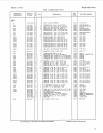
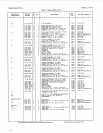
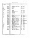
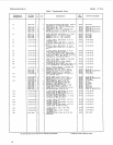
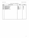
Ordering Information
To
order a part listed in the replaceable parts table, include the Hewlett-Packard part number (with the
check digit) and the quantity required. Address your order to the nearest Hewlett-Packard office. The
check digit will ensure accurate and timely processing of your order. To order a part that is not listed in
the replaceable parts table, include the instrument model number, instrument serial number, description
and function of the part, and the quantity of parts required. Address the order to the nearest
Hewlett -Packard office.
31.
Manual Changes
These paragraphs contain manual change instructions for backdating this manual for HP Model
Microwave Converters with the serial number prefix 2407A.
1793A
Instruments with Serial Prefix 2407A have System I1 cabinet parts and hardware that are English thread.
Instruments with Serial Prefix 2520A and higher have System I1 cabinet parts and hardware that are
METRIC thread.
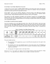
In Table
7.
Replaceable
PUY~S,
both English and Metric thread part numbers are listed for the System I1
cabinet parts. These correct part numbers are referenced under the instrument’s serial number prefix.
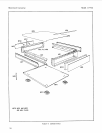
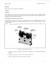
Instruments with the serial number prefix 2407A have MP3 (rear frame), MP8 (rear panel), and associated
english thread hardware, that are screwed together. These parts have been changed to a riveted, one piece
assembly that
is
referenced to MP8. To replace MP8 you must order the Rear Panel Assembly
1
1793-20009, and the metric screws for the side struts and rear feet.
32.
SERVICE
33.
Principles of Operation
Simplified
Block
Diagram
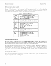
A
simplified block diagram of the Microwave Converter is shown in Figure
10.
The signal at the RF
INPUT connector is routed through an input switch either to the Direct Path (and out the IF OUTPUT
connector), or to the Down-Convert Path. The Down-Convert Path has a
3
dB RF Attenuator (to improve
input
SWR),
a
Mixer (tte down-converter), an IF Low-pass Filter (to remove the
sum
component of the
mixing process while passing the difference component), and a
+1S
dB IF Amplifier (to restore signal loss
through the Down-Convert Path).
Usually, the
LO
frequency selected is higher than the frequency of the input signal. (The measuring
instrument assumes this.) The difference frequency (the IF) is filtered by the IF Low-Pass Filter, which
has a
3
dB corner of
800
MHz. The IF should be kept between the range of 10 and 700 MHz.
If the instrument has the optional LO Amplifier installed, the measuring instrument automatically
switches in the amplifier whenever an LO frequency greater than
18
GHz is selected.
23