


18
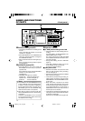
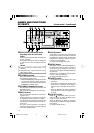
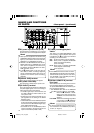
^ DC power input terminal (2-PIN)
This terminal is for inputting DC 12 V. Connect
the DC power cord of the supplied AC adapter.
& [SIGNAL GND] terminal
This is the grounding terminal for signals.
* DC power cord clamp
Use this clamp to fasten the DC power cord.
( [DV IN/OUT] terminal
This is the input/output terminal for IEEE1394-
compliant digital signals. It is for connecting to
video equipment with a DV terminal.
•To enable signal input via this terminal, set
the INPUT SELECT switch located on the
front panel to “DV”.
• Signals that come from this terminal are out-
put regardless of the setting of the INPUT
SELECT switch.
• If REPLICATION of the SYSTEM (2/2) Menu
is set to DV, the REC command is output from
this terminal when BR-DV6000 begins play-
back. (REPLICATION mode)
• Set PB/DV IN in the SYSTEM(2/2) Menu
screen according to the signal format to be
input to this terminal. (NTSC or PAL)
NAMES AND FUNCTIONS
OF PARTS
– Rear panel – (continued)
Memo
● When power is supplied to this terminal, the
OPERATE indicator located on the front panel
lights up. (The indicator turns red when BR-
DV6000 is in the OPERATE OFF state)
● Whether to set BR-DV6000 to enter the OP-
ERATE ON mode or OPERATE OFF mode
when power is supplied to the terminal can
be selected with DC IN MODE in the SYS-
TEM (2/2) Menu screen.
● If the ) TIMER switch on the rear panel is
set to “REC” or “PLAY”, recording or playback
will be automatically started when power is
supplied to the terminal. (Timer recording/
playback)
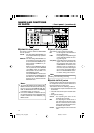
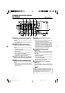
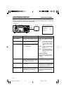
) [TIMER] recording/playback
switch
This switch is for setting BR-DV6000 to start
timer recording or timer playback when power
is supplied to the ^ DC power input terminal
according to an external timer.
OFF : No timer recording or timer playback.
REC : When power is supplied, BR-DV6000
starts recording automatically.
(Timer recording)
PLAY : When power is supplied, BR-DV6000
starts playback automatically.
(Timer playback)
Memo
● To use this terminal as the foot switch input,
set FOOT SW in the REMOTE (2/2) Menu
screen. (☞ Page 77)
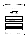
VIDEO
LINE
IN
OUT
MONITOR
OUT
DC12V
DV
IN/OUT
IN OUT
OFF
AUDIO
REMOTE2
IN
B-YR-Y
SYNC IN
TIME CODE
IN OUT
Y
COMPONENT
OUT
CH 1/3 CH 2/4
IN
OUT
MONITOR
OUT
REMOTE1
TIMER
REC PLAY
SERIAL
REMOTE
SIGNAL
GND
Y/C
&
fi
*
^ ( ⁄ ¤ )‹
›
Memo
● If the TIMER switch is set to “REC” or “PLAY”,
BR-DV6000 automatically enters the OPER-
ATE ON mode upon DC power on even when
DC IN MODE in the SYSTEM (2/2) Menu
screen is set to “OPE OFF”.
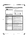
⁄ [SERIAL REMOTE IN] terminal
(mini jack)
This terminal is for connecting to the serial re-
mote controller RM-G30 (sold separately).
To operate BR-DV6000 with this terminal, per-
form the following settings.
• Set REMOTE SEL SER in the REMOTE
(1/2) Menu screen to “ON” or “LOC+REM.”
ON : When the 4 REMOTE / LOCAL
switch on the front panel is set to
“REMOTE”, this terminal becomes
effective.
LOC+REM: This terminal is effective regardless
of the setting of the 4 REMOTE /
LOCAL switch on the front panel.
DV6000U_02-027_Eng.p65e 06/03/03, 11:39 PM18