


22
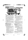
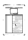
32K CH–1/2 0SP mi n00
ASSEM
W
ARNING 7001
DRUM MOTOR FA I LURE
REC I NH I B I T
03/04 /03 STANDBY
-
OFF
11:20 :00 TCR 02:00:00:00
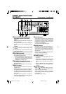
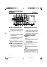
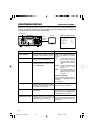
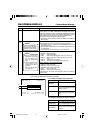
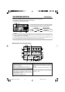
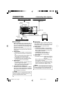
ON-SCREEN DISPLAY – Status display – (continued)
No. Item Description
3
Counter display Displays the CTR counter, time code or user’s bit. The dis-
played contents can be selected using the COUNTER switch.
• CTL counter: It will be displayed if the COUNTER switch is
set to CTL. The counter shows a 7-digit
number (hour, minute, second and frame) with
+ or – and “CTL” at the beginning, e.g., CTL-
9:30:20:10
• Time code : It will be displayed if the COUNTER switch is
set to TC. The time code shows an 8-digit
number (hour, minute, second and frame).
At playback, the time codes recorded on the
tape are displayed.
The prefix indicates the time code mode.
TCG : Time code generator data
TCR : Time code reader data
DTCG : Time code data received from the DV IN / OUT
terminal
ETCG : External time code generator data
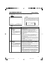
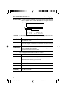
Depending on the framing mode, the symbols for the sec-
onds and frames are different (only for NTSC).
00 : 00 : 00 : 00
Dot (.) for the drop frame mode
¥ Colon (:) for the non-drop frame mode
• User’s bit : it will be displayed if the COUNTER switch is
set to UB.
The user’s bit is an 8-digit number (each digit
is a number or character from 0 – F).
The prefix indicates the user’s bit mode.
UBG : User’s bit generator data
UBR : User’s bit reader data
DUBG : User’s bit reader data received from the DV IN /
OUT terminal
EUBG : External user’s bit generator data
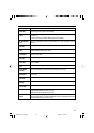
Memo
● The position of the counter display can be changed with
COUNTER POSI in the DISPLAY Menu screen.
● The counter display can be turned on/off with TIME
CODE in the DISPLAY Menu screen.
DV6000U_02-027_Eng.p65e 06/03/03, 11:39 PM22