


92
RXD
0AH
EDH
0AH
01H
0AH
D1
7654321
01EXTERNAL :
0
D2
DATA0
0AH
D2
TXD
RXD
01HD3H
0AH
D1
7654321
1 1
0 1
AUTO :
EXTERNAL :
0
D2
D2
TXD
DATA0
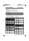
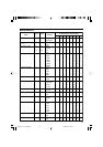
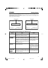
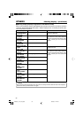
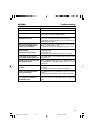
RS-232C INTERFACE – RS-232C commands – (continued)
E7
8E
8F
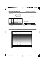
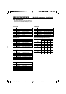
TIMER MODE SELECT :
For selecting the counter mode. Fol-
lowing this command, send 1-byte
data corresponding to the counter
mode.
DATA SELECT :
For setting the date. Following this
command, send 6-byte numeric data.
Specify month, date and year (in this
sequence) with two digits for each.
TIME SELECT :
For setting the time. Following this
command, send 6-byte numeric data.
Specify hour, minute and second (in
this sequence) with two digits for each.
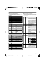
1
2
5
TC
CTL
UB
Low
High
Counter mode
3
(Fixed)
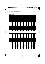
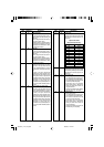
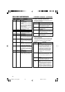
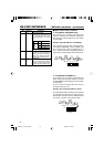
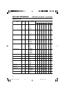
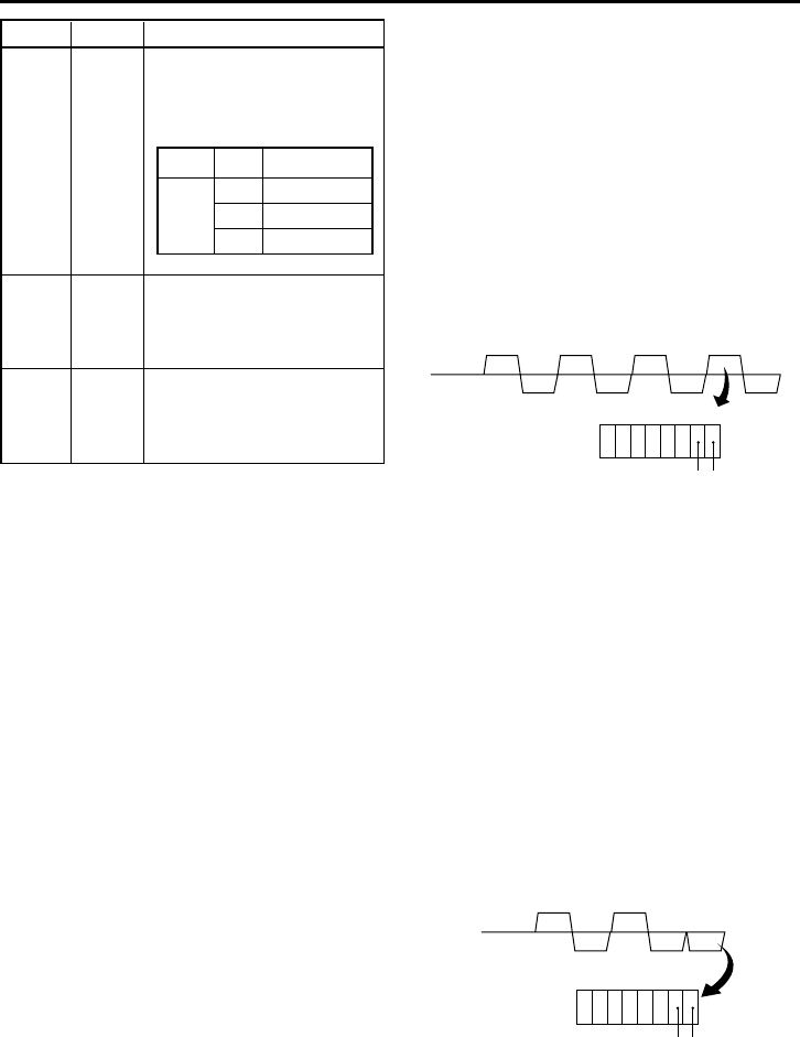
Ⅵ Menu switch setup command
● ED: MEMORY SW PRESET (B/J1)
This command is for changing the VCR’s menu
switches. Following this command, transmit the
data (3 bytes) corresponding to the menu switch
to be changed.
Example: Set SYNC SELECT to EXTERNAL.
In the diagram below, the data corresponding to
the setting of EXTERNAL show that DATA 0, D2
No. 1 bit and D2 No. 0 bit are, respectively, 01, 0
and 1. Set the command by transmitting data in a
way that the corresponding bit values match them.
Bit No.
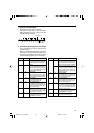
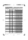
● D3: MEMORY SW SENSE (J1)
This command is for checking the VCR’s menu
switch setting. Following this command, transmit
the data (DATA0) corresponding to the menu switch
to be checked.
You can confirm the setting with the bit count of
the returned data (D1, D2).
Example: Check the SYNC SELECT setting.
As in the diagram below, the setting can be checked
by confirming the values for the menu switch. In
this example, check the values for DATA0 (namely
01), D2 No. 1 and No. 0 of the returned data.
Bit No.
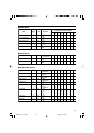
Table Command Description
DV6000U_72-104_Eng.p65e 06/03/03, 11:42 PM92