


Masterpage:Right-index2
7
Filename [HM-HDS4EK_03Names.fm]
Page 7 April 24, 2003 9:35 am
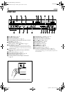
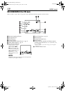
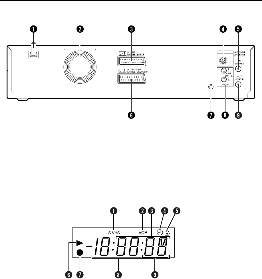
REAR VIEW
SAT CONTROL
CONTROLEUR SAT
S VIDEO
OUT
SORTIE
A
Mains Power Cord
੬
pg. 12
B
Cooling Fan
●
This prevents the temperature from rising inside the
recorder. Do not remove it.
●
Install the recorder so as not to block the area around the
fan.
●
The fan may be activated even if the recorder is turned off.
C
L-1 IN/OUT Connector
੬
pg. 12, 68, 70, 75, 76
D
S VIDEO OUT Connector
੬
pg. 13
E
ANTENNA IN Connector
੬
pg. 12
F
L-2 IN/DECODER Connector
੬
pg. 18, 70, 75,
76
G
SAT CONTROL Connector
੬
pg. 18
H
AUDIO OUT (L/R) Connectors
੬
pg. 13, 77
I
ANTENNA OUT Connector
੬
pg. 12
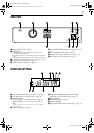
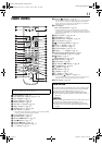
FRONT DISPLAY PANEL
A
S-VHS Indicator (S-VHS deck only)
੬
pg. 80
B
VCR Indicator (S-VHS deck only)
੬
pg. 76
C
Channel/Clock
Remain Display (S-VHS deck only)
੬
pg. 43
Mode Display (L-1, L-2 (or SAt*), F-1, d-1, or
dub)
* When “L-2 SELECT” is set to “SAT” (
੬
pg. 69), “SAt” appears
instead of “L-2”.
D
“Timer” Indicator
੬
pg. 47
E
Automatic Satellite Programme Recording
Indicator
(
N
)
(S-VHS deck only)
੬
pg. 51
F
Play Indicator
G
Record Indicator
੬
pg. 33
H
Counter Display
I
Tape Speed SP/LP (S-VHS deck only)
੬
pg. 34
HM-HDS4EK_03Names.fm Page 7 Thursday, April 24, 2003 9:38 AM