


Filename [M100_05Name.fm]
Masterpage:Left0
12 EN
INDEX
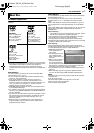
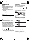
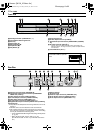
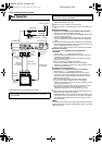
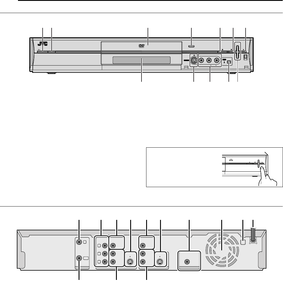
Front View
A Standby/On Button (STANDBY/ON A)
B Infrared Beam Receiving Window
C Disc tray
D Eject Button (M)
E Record Button (R)
F Stop Button (o)
G Play Button (I)
H Front Display Panel
I S-video Input Connector [S-VIDEO]
J Video/Audio Input Connectors [VIDEO/AUDIO (L(MONO)/
R)]
K DV Input connector [DV IN (A*)]
* i (i.Link) refers to the IEEE1394-1995 industry specification and
extensions thereof. The i logo is used for products compliant with the
i.Link standard.
L Channel Buttons (CH +/–)
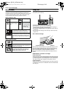
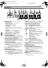
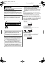
Rear View
A Antenna Input Connector [ANTENNA IN]
B Component Video Output Connectors [COMPONENT
VIDEO OUT (Y/P
B
/P
R
)]
C Video Output Connector [VIDEO OUTPUT]
D S-video Output Connector [S-VIDEO OUTPUT]
E Video Input Connector [VIDEO INPUT L-1]
F S-video Input Connector [S-VIDEO INPUT L-1]
G Digital Audio Output Connector [DIGITAL OUT (COAXIAL)]
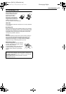
H Cooling Fan
● This prevents the temperature from rising inside the unit. Do not
remove it.
● Install the unit so as not to block the area around the fan.
● The unit may become hot when it is turned off, as the cooling
fan on the rear of the unit is not activated. However, the cooling
fan may be activated in the following cases;
^ In the Automatic Satellite Program Recording standby mode
(A pg. 42).
^ When AAUTO CLOCKB is set to AONB (A pg. 19).
(Set AAUTO CLOCKB to AOFFB if you mind the noise of the
fan.)
I Region Number
J AC Power Cord
K Antenna Output Connector [ANTENNA OUT]
L Audio Output Connector [AUDIO OUTPUT]
M Audio Input Connector [AUDIO INPUT L-1]
STANDBY/ON
RAM/RW
CH
+
F
-
1
S
-
VIDEO VIDEO L(MONO) AUDIO R
DV
DVIN
CB D E F GA
HI
J K L
To access covered connectors,
press PUSH-OPEN to open the
cover.
CH
+
CH
-
PUSH-OPEN
DIGITALOUTINPUTOUTPUTANTENNA
PCM/STREAM
COAXIAL
L-1
L-1
RIGHT
VIDEO
AUDIO
LEFT
RIGHT
VIDEO
AUDIO
LEFT
S-VIDEOS-VIDEO
COMPONENT
Y
P
B
P
R
IN
OUT
ABC D E F G IH J
K L M
M100_00.book Page 12 Friday, February 18, 2005 6:23 PM