


18
INSTALLATION AND CONNECTION
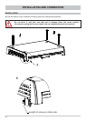
INSTALLATION OF THE UFS 940SW
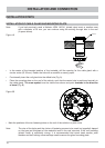
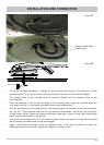
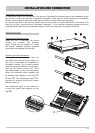
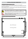
The four screw sockets provided (see diagram on the next page) allow you to install the receiver not
only resting on a shelf but also to fi x it there or in other positions.
INSTALLATION AND CONNECTION
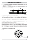
Note: When choosing the installation location, bear in mind that the rear of the unit should
always be accessible. The UFS 940sw is equipped with a power saving circuit and a
separate infrared transmitter, which means that the unit does not need to be placed
where it is visible. You can therefore fi t the UFS 940sw out of sight in any location,
e.g. on cupboard walls, side walls or the base of storage compartments.
In addition, the following points should be taken into account:
• The wall thickness at the installation location must be at least 15 mm, as otherwise the screws will
break through on the other side or damage the surface
• Ensure that the cupboard or storage compartment in which the unit is to be housed is adequately
ventilated to prevent a build up of heat. Carpet-covered walls are unsuitable for installation
• Take care when tightening the screws not to damage any cables etc. behind or in the wall
• The receiver is designed exclusively for installation in dry, interior locations. The installation location
must be protected against moisture
• The cable lengths must be taken into account when choosing the installation location
• The connecting cables must be provided with strain reliefs
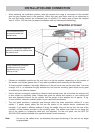
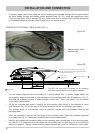
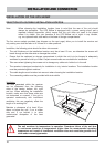
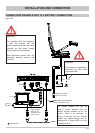
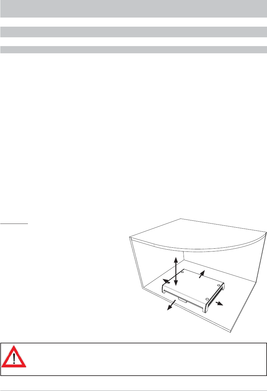
Ventilation:
The heat generated within the receiver
can be dissipated from the following
sides of the casing: bottom, left, right
and top. When selecting the installation
location, make sure that these sides are
not obstructed or covered. If the unit is
operated continuously with insuffi cient
ventilation, this can negatively affect the
length of its working life!
Maintain a clearance of at least 20 cm
above or below the unit, 2 cm to either
side and 5 cm behind it, to allow
unobstructed dissipation of the heat
generated.
Minimum
clearance
20 cm
2 cm
2 cm
5 cm
5 cm
SELECTION OF A SUITABLE INSTALLATION LOCATION
The unit monitors its temperature in operation. Premature failure of the unit due
to continuous operation at temperatures higher than the recommended operating
temperature as a result of insuffi cient ventilation does not constitute grounds for a
claim under warranty/guarantee.