


Connection Diagram
62
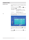
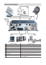
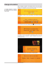
SAT-ZF Connection
The coaxial cable coming from the antenna is connected to the SAT-IF
input on the UFD 170. The SAT-IF output on the UFD 170 control unit is
already connected to the SAT-IF input on the UFD 170 receiver with the
coaxial cable supplied. The correct sequence must be observed due to
the power supply for the LNB (via coaxial cable) and communication
between the two boards in the UFD 170 (control unit and receiver).
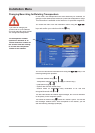
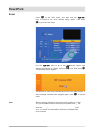
On-Board Network Connection
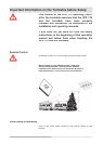
In terms of the on-board network connection, refer to the
information in the installation manual for the CAP 210/310.
The power supply cable supplied (wires: brown/white/green) is
connected directly to the battery (battery strip before fuse). The
brown wire is connected to “+”, the white wire to “-” and the green
wire to the ignition behind the ignition lock, so that it is under
power as soon as the ignition is switched on. Make sure that the
“+ 12 V”, “earth” and “ignition” wires cannot be interrupted by switches
connected in series, as this can disable the function for automatic
lowering of the antenna.
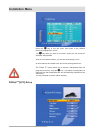
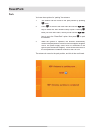
The green connection is important as it is the only way to ensure that
the turntable moves to park position when the ignition is switched on.
This prevents driving with the antenna extended.
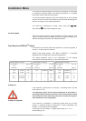
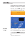
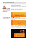
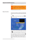
If the supply voltage is too low, the UFD 170 receiver displays the OSD
message “On-board voltage too low”. If the on-board voltage is too low,
other error messages can also appear (e.g. “Overload”, even though
there is no overload).
Control Cable
The control cable for the turntable is connected to the UFD 170 (see
previous page).