


2 Installation
TracVision 4 is designed for simple installation and setup. Just
follow these easy steps:
Step Refer to Section...
1. Choose the hardware locations 2.1
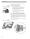
2. Mount the Antenna Unit 2.2
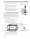
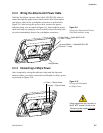
4. Wire system components 2.3
5. Select active satellite 2.4
6. Check out system 2.5
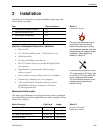
Materials and Equipment Required for Installation
• Electric drill
• 3/8" (10 mm) drill bits and 3" (80 mm) hole saw
• Socket wrenches
• Flat tip and Phillips screwdrivers
• RG-6 (75 ohms) cable for a second RF Signal Cable
(if necessary)
• Light hammer; center punch; adhesive tape;
scriber or pencil
• Power cable to connect ship’s power to switchplate
• Terminal lug crimping tool; wire strippers
• A PC with terminal emulation software such as
PROCOMM, Windows Terminal, or Windows
95/98 Hyperterminal.
Below-decks Cable Lengths
The major considerations in locating the below-decks equipment
are accessibility and cable lengths between units. Lengths of these
cables are as follows:
Cable (Function) KVH Part # Length
Data Cable (IRD to Antenna Unit) 32-0619-50 15 m (50 ft)
Power Cable (Power to Antenna Unit) 32-0510-50 15 m (50 ft)
RF Cable (Antenna to IRD) 32-0417-50 15 m (50 ft)
IRD Ground Wire 32-0583-50 15 m (50 ft)
2-1
Installation
54-0150 Rev. D
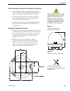
Plan the entire installation before
proceeding! Take into account
antenna unit placement, running
cable distances between units, and
accessibility to the equipment after
installation. Cable lengths are
detailed in Table 2-2.
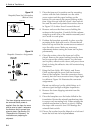
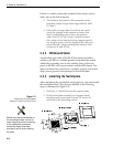
KVH recommends the use of RG-6
(75 ohms) cable for RF wiring. Use
of non-RG-6 (75 ohms) cables will
result in degraded performance.
The KVH warranty does not cover
degraded performance due to
improper wiring.
Table 2-1
Installation Process
Table 2-2
Lengths of Provided
Below-decks Cables