


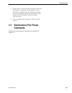

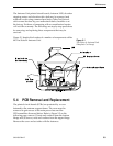
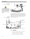
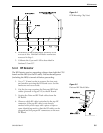
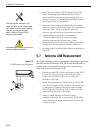
The PCBs are mounted to the antenna elevation mechanism
support frame with machine screws and are interconnected by
means of keyed Molex connectors. Figure 5-3 shows the PCB
arrangement, connector locations, and functions while Figure 5-4
on the next page shows how the printed circuit boards are
mounted to the support frame.
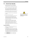
5.4.1 CPU Board
1. Remove the seven Molex connectors from the CPU.
2. Remove eleven #6-32 x 3/8" machine screws,
lockwashers and flat washers from the PCB.
3. Remove the assembly from the main support.
5-4
A Guide to TracVision 4
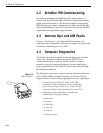
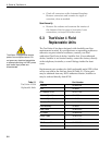
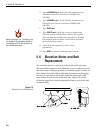
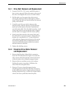
Figure 5-2
PCB Cover Plate Removal
PCB Cover
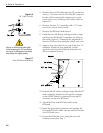
Azimuth
Motor
(J1)
Elevation
Motor
(J2)
Azimuth/Elevation
Switch (J5)
External Sensor (J3)
RF PCB (J9)
Antenna Gyro (J11)
Power Data (J4)
Fuse
Figure 5-3
PCB Connector Locations
(Rear View)
The PCB cover fits snugly over the
PCB. When removing or replacing
the cover, take care to ensure that
the cover does not dislodge any of
the Molex connectors as this will
cause system errors and improper
operation.