


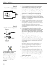
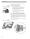
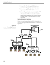
11. Apply a flat washer and lock nut from
underneath.
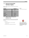
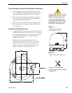
12. Tighten securely until the foam seal is compressed
as far as it will go and all four feet are bottomed
against the mounting surface, as illustrated in
Figure 2-5.
13. Replace the radome over the baseplate. Align the
radome screw holes with the nut holders, insert
the screws and tighten. Install a protective plastic
screw cap from the kitpack over each screw.
Several spare protective caps are provided.
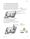
2.3 Wiring the TracVision 4 System
A switchplate has been provided to serve as the hub of the
TracVision 4 wiring (with the exception of the RF cable, which
will be connected to the IRD). This switchplate includes an
ON/OFF switch and a DB9 maintenance port for easy access to
the Antenna Unit’s software and diagnostics. Follow these steps
to begin the wiring process.
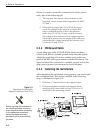
1. Select a location to mount the TracVision 4
switchplate. It should be flat and within reach of
the cables connected to the Antenna Unit.
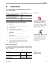
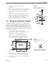
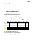
2. Create a panel cutout in the mounting surface.
Figure 2-6 illustrates the mounting dimensions
and a template has been provided in Appendix C.
3. Run the Antenna power and data cables from the
Antenna Unit and out through the panel cutout.
4. Run a cable from ship’s power (11-16 Vdc) through
the panel cutout.
2-5
Installation
54-0150 Rev. D
Figure 2-5
Bolting the Antenna Unit to
the Deck (Side View)
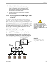
A full-scale panel cutout template
has been provided in Appendix C.
Figure 2-6
Switchplate Panel Cutout
Dimensions