Tips for Successful Antenna Unit Placement and Mounting
• The mounting surface should be essentially flat,
free of vibration and flexing, and strong enough to
carry the complete assembly (30 lbs/13.6 kg).
• The antenna unit need not be located exactly on
the vessel’s fore-and-aft axis, but its centerline
reference MUST be parallel to it.
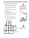
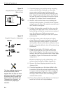
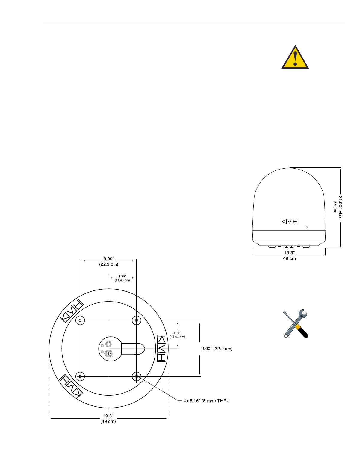
• Be sure to account for the radome height and the
base dimensions, illustrated in Figures 2-1 and
2-2 respectively.
Antenna Unit Mounting Procedure
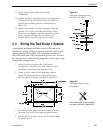
1. Using the base dimensions presented in Figure 2-2
or the template provided in Appendix B, lay out the
four mounting bolt holes. Check the layout of the
baseplate to ensure that it is parallel with the
vessel’s fore/aft axis.
2. Drill four 3/8" (10 mm) bolt holes. Mark a
3" (80 mm) diameter circle in the center of the
pattern and cut out to make a passage for the
cables to connect to the baseplate. Smooth the
edges of the hole to protect the cables.
2-3
Installation
54-0150 Rev. D
Always lift the antenna unit by the
gray baseplate structure, not the
radome. Also be careful not to
strike the exposed connectors
extending from the bottom of the
baseplate or allow them to carry
the weight of the antenna unit.
Figure 2-1
Antenna Unit Elevation
and Baseplate Diameter
Figure 2-2
Antenna Unit Base Dimensions
A template of the baseplate
mounting holes has been provided
in Appendix B.


