5. Type =CALAZ<cr>. Verify that the Antenna Gyro
Azimuth scale factor is between 0.000800 and
0.001200.
6. Type
=CALEL<cr>. Verify that the Antenna Gyro
Elevation scale factor is between 0.000800 and
0.001200.
7. Type
ZAP<cr>.
8. Type
HALT<cr> while the system is performing
the limit switch initialization routine. The system
will complete the initialization function by finding
the azimuth and elevation switch limits and then
go to the home position.
9. Verify that the response has the correct
parameters.
10. Type
ZAP to restart/reinitialize the system.
5.6 Elevation Motor and Belt
Replacement
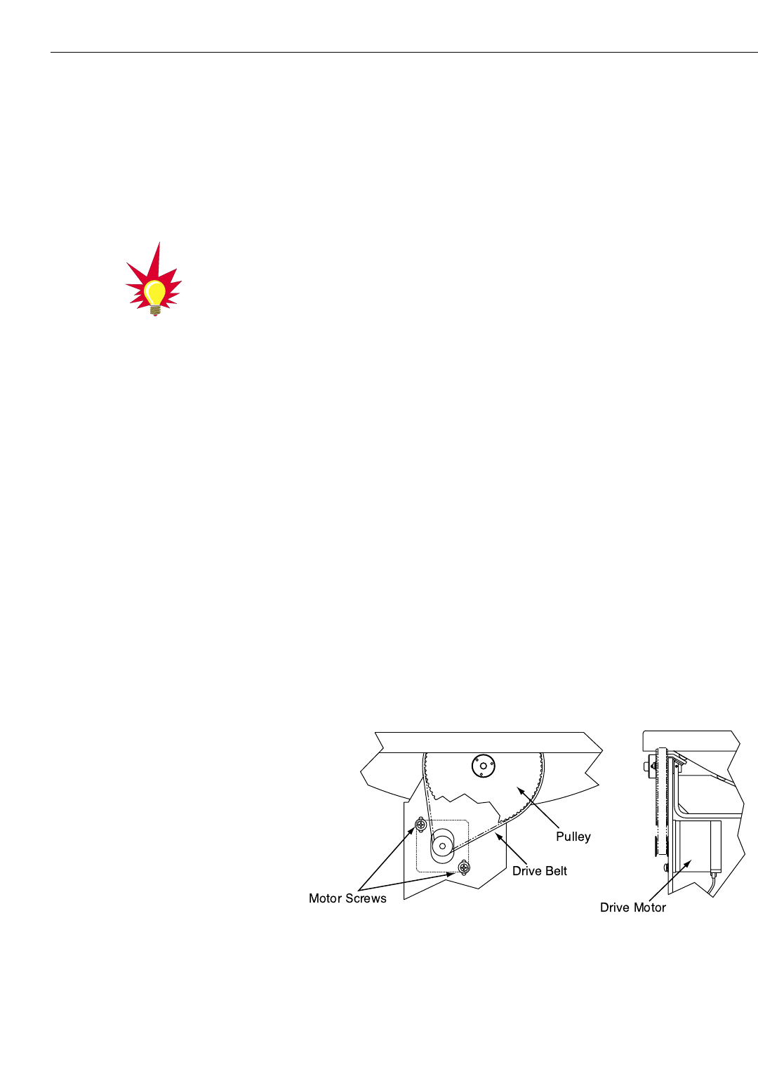
The elevation motor is mounted to the inside of the elevation
drive assembly support frame. Machine screw/washer sets hold
the drive motor in proper position to maintain proper tension on
the toothed drive belt. When adjusting belt tension or changing
the belt, do not remove the screws from the motor side, only
loosen the external screws on the belt side. Figure 5-8 on the
following page shows the arrangement of motor, drive belt, and
antenna pulley.
5-8
A Guide to TracVision 4
Figure 5-8
Elevation Drive Mechanism
Refer to Section 2.4, “Checking Out
the System” for complete details in
connecting a PC to the system via
the maintenance port.
