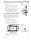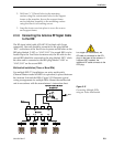
2. Drill four
3
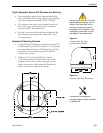
⁄32" (2.5mm) holes in the mounting
surface using the countersunk holes in the support
frame as the template. Secure the support frame
and switchplate assembly to the mounting surface
using the four #6 self-cutting screws.
3. Snap the front cover into place to cover the screws
and support frame.
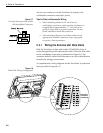
2.3.6 Connecting the Antenna RF Signal Cable
to the IRD
The RF signal cable (cable #32-0417-50) is fitted with F-type
connectors. One end should be connected to the plug labeled
“RF1” on the base of the TracVision 4 system and the other to the
IRD plug labeled “LNB” or “ANT/SAT.” If a second IRD is to be
hooked up to the TracVision 4 antenna unit, the RF cable for the
second IRD should be connected to the plug labeled “RF2” while
the other end is connected to the IRD plug labeled “LNB” or
“ANT/SAT” on the second IRD.
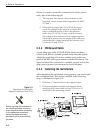
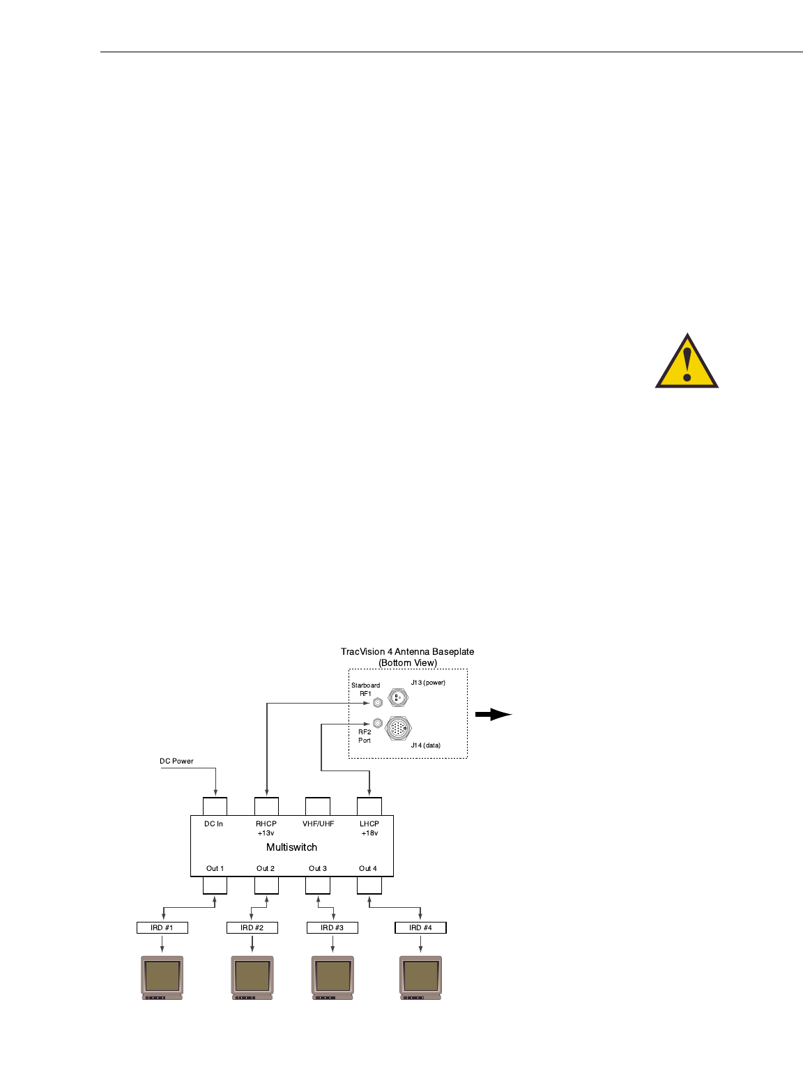
Multiswitch Installation (Three or More IRDs)
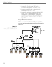
For multiple IRD/TV installations, an active multiswitch
(Channel Master model 6214IFD or equivalent) is placed between
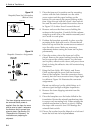
the Antenna Unit and the IRDs. Figure 2-12 illustrates typical
wiring arrangements for multiple IRDs. Mount the multiswitch
unit in accordance with the manufacturer’s instruction sheet.
2-9
Installation
54-0150 Rev. D
Bow
Figure 2-12
Connecting Multiple IRDs
using an Active Multiswitch
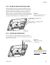
For single IRD installations, the
RF cable is connected to the RF1
plug on the base of the antenna. If
a second IRD is added, the
additional RF cable connects to the
RF2 plug.


