2-8
If there is a need to extend the Antenna Unit-to-ship’s power
cable, refer to the following tips:
• The Antenna Unit power cable connector on the
baseplate cannot accept cables larger than 14 AWG
(1.5 mm
2
).
• If the cable is longer than 15 m (50 ft), be sure to
verify the voltage at the antenna to ensure that
there is sufficient power to drive the antenna
under load (11-16 Vdc). If not, carefully increase
the voltage to the Antenna Unit to compensate for
any drop in power over the length of the cable and
ensure that the voltage reaching the Antenna Unit
is between 11 and 16 Vdc.
2.3.4 IRD Ground Cable
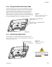
A grounding wire (cable #32-0583-50) has been provided to
connect your IRD to a suitable ground and protect the system.
Attach the grounding wire to any suitable screw on the rear
panel of the IRD with a good contact with the IRD chassis. The
other end should be connected to a suitable ground, such as the
ship’s power ground wire connected to the switchplate.
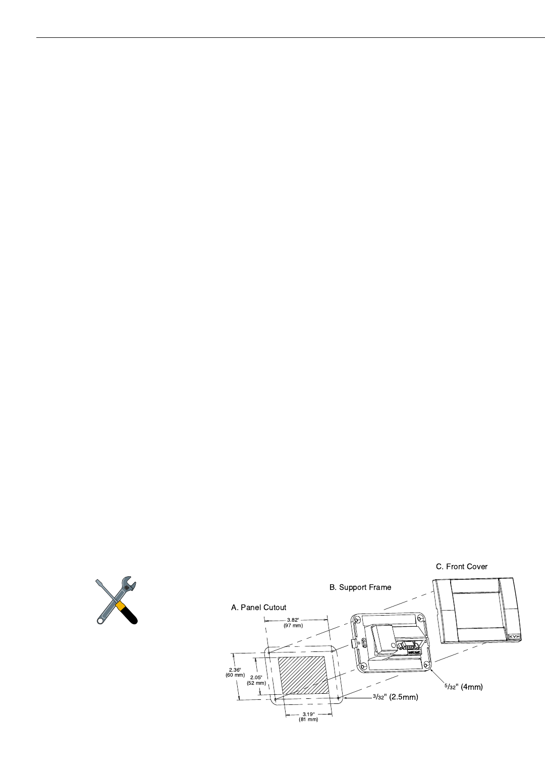
2.3.5 Installing the Switchplate
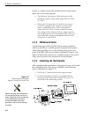
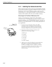
After completing the switchplate wiring process, you must install
the switchplate itself. This process, detailed in the following
steps, is illustrated in Figure 2-11.
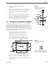
1. Drill four
5
⁄32" (4mm) holes in the support frame.
2. Fit the switchplate assembly and support frame
into the panel cutout made in Step 2 in Section 2.3
and flush to the mounting surface.
A Guide to TracVision 4
Figure 2-11
Mounting the Switchplate
Support Frame and Front Cover
Before securing the switchplate to
the mounting surface, be sure to
strain relieve the wires connecting
to the switchplate connectors.
several tie-wraps have been
provided to aid in strain relieving
the wires.


