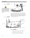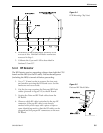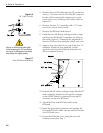
• Check all connectors at the Antenna Baseplate.
Remove connectors and examine for signs of
corrosion; clean as needed.
Semi-Annually
• Remove the radome and examine the interior of
the Antenna Unit for signs of corrosion, loose
connections, or frayed or broken wires.
5.3 TracVision 4 Field
Replaceable Units
The TracVision 4 has been designed with durability and low
maintenance in mind. If you experience an operating problem or
otherwise require technical assistance, contact your local
authorized TracVision 4 dealer/installer first. If an authorized
dealer/installer is not located nearby, contact the factory directly
at the telephone, facsimile, or e-mail listings inside the front
cover.
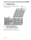
Replacement part numbers for field replaceable units (FRUs) that
can be serviced in the field are listed in Table 5-1. These parts
may be obtained from any KVH authorized dealer/installer or
may be ordered directly from KVH.
FRU Part Number
Radome 02-0925-04
CPU 02-0992
RF Detector PCB 02-1017-02
Antenna Gyro Sensor 02-1035
Antenna Gyro Gasket 24-0139
Elevation Drive Belt 24-0105-83
LNB Assembly 02-0932
Data Cable 32-0619-50
PC Cable 32-0628-06
Power Cable 32-0510-50
RF Cable 32-0417-50
IRD Ground Wire 32-0583-50
CPU Fuse 16-0017-4000
5-2
A Guide to TracVision 4
Table 5-1
TracVision 4 Field
Replaceable Units
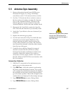
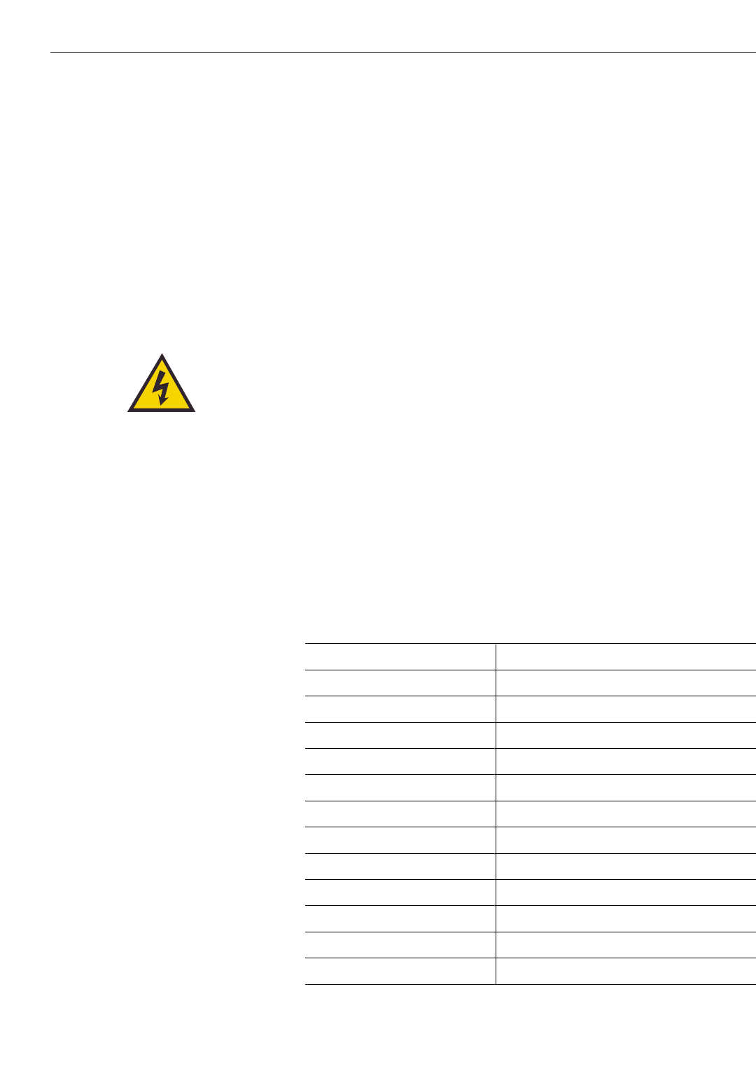
TracVision 4 components receive
power from multiple sources. Do
not open any electrical assemblies
or attempt servicing until IRD power
and vessel input power are
disconnected.


