PAGE 11
MS300 User’s Manual
for bit duplicates of the original.
• Guide - a grid or list of information, used to browse your media library.
• Player - the screen used to display the currently playing media.
5. POWER UP!
• Plug each changer into an AC outlet.
• Plug the MS300 into an AC outlet.
• The Standby LED on the front of the MS300 will begin to flash RED during
the power on cycle. When the LED turns solid RED, the MS300 is ready
for use.
• Press the power button on the front panel or on the remote control. The
LED will turn Off and video will be displayed on the TV when the
unit is on.
Note: You may have to press the "MS1" button on the remote to configure it to control the MS300.
Also be sure the TV and receiver are turned on and set to the correct the MS300 input.
6. QUICK START
• Use the remote control and follow the on-screen instructions.
• If you have more than one changer, repeat these steps to connect the
additional changers to communications ports and audio jacks 2 and 3
respectively.
• For the best audio quality, you should also connect digital optical audio
cables between your changers and the MS300.
4. CONNECT THE MS300 TO THE INTERNET
MS300 requires an Internet connection to identify the discs in connected changers, to provide
additional entertainment services, and for general system maintenance.
• If you do not have an ethernet network connected to the internet and you
would like to use Dialup Internet Access, you will need to connect an
external modem (not included) to COM port 4 and connect the modem to a
working phone line. Contact your McIntosh Dealer for details.
• If you have a broadband (cable, DSL, ISDN) Internet Service Provider
,
connect an ethernet cable from the MS300's ethernet jack to your
ethernet network.
NOTE: You may need to purchase additional network hardware such as a "router". Please
contact your McIntosh Dealer for more information.
1. UNPACK YOUR NEW MS300
• Unpack the MS300 and accessories (save the box).
• Install the included batteries into the remote and keyboard.
• Make note of the serial number (located on the back).
SERIAL NUMBER: _________________________________________
2. CONNECT THE MS300 T
O YOUR AUDIO SYSTEM
A) Obtain the proper connecting cables from your McIntosh Dealer.
B)
Connect the MS300 to any available A/V input on your receiver or TV.
Note: You may use optional s-video or component video cables and optional digital
audio cables for the best picture and sound quality. This is also applicable to the next
step, connecting changers to your MS300. Contact your McIntosh Dealer for more
information.
3. CONNECT OPTIONAL CHANGERS TO YOUR MS300
SONY CD CHANGERS
The MS300 requires that you connect each Sony CD changer to the back panel using
audio and S-Link control cables.
Follow these steps to connect your Sony CD changers to your MS300:
1. Locate the S-Link cable, with 1/8” male plugs on each end.
2.
Connect one end of the S-Link cable into the S-Link/IR Out jack number 1
on the back of your MS300.
3.
Connect the other end of the S-Link cable into the Control A1 jack on the
back of your changer.
4.
Locate a stereo RCA audio patch cable. .
5.
Connect one end of the RCA audio cable into the Analog In jacks number
1 on the back of your MS300.
6.
Connect the other end of the RCA audio cable into the Analog Line Out
jacks on the back of your changer.
• If you have more than one changer, repeat these steps to connect the
additional changer to S-Link and audio jack 2.
• For the best audio quality, you should also connect digital optical audio
cables between your changers and the MS300.
• Make sure that all changers are set to COMMAND MODE 1.
SONY, KENWOOD, OR PIONEER CD/DVD CHANGERS
The MS300 requires that you connect each CD/DVD changer to the back panel using
audio and RS-232 control cables. NOTE: The MS300 supports only CDs in these
changers. Do not install DVDs.
Follow these steps to connect your CD/DVD changers to your MS300:
1.
Locate the proper RS-232 serial cable for your changer.
2.
Connect one end of the RS-232 serial cable into Communication Port
number 1, on the back of your MS300.
3.
Connect the other end of the RS-232 serial cable into the “RS-232C” port
on the back of your changer.
4.
5.
Connect one end of the RCA audio cable into the Analog In jacks number
1 on the back of your MS300.
6.
Connect the other end of the RCA audio cable into the Analog Line Out
jacks on the back of your changer.
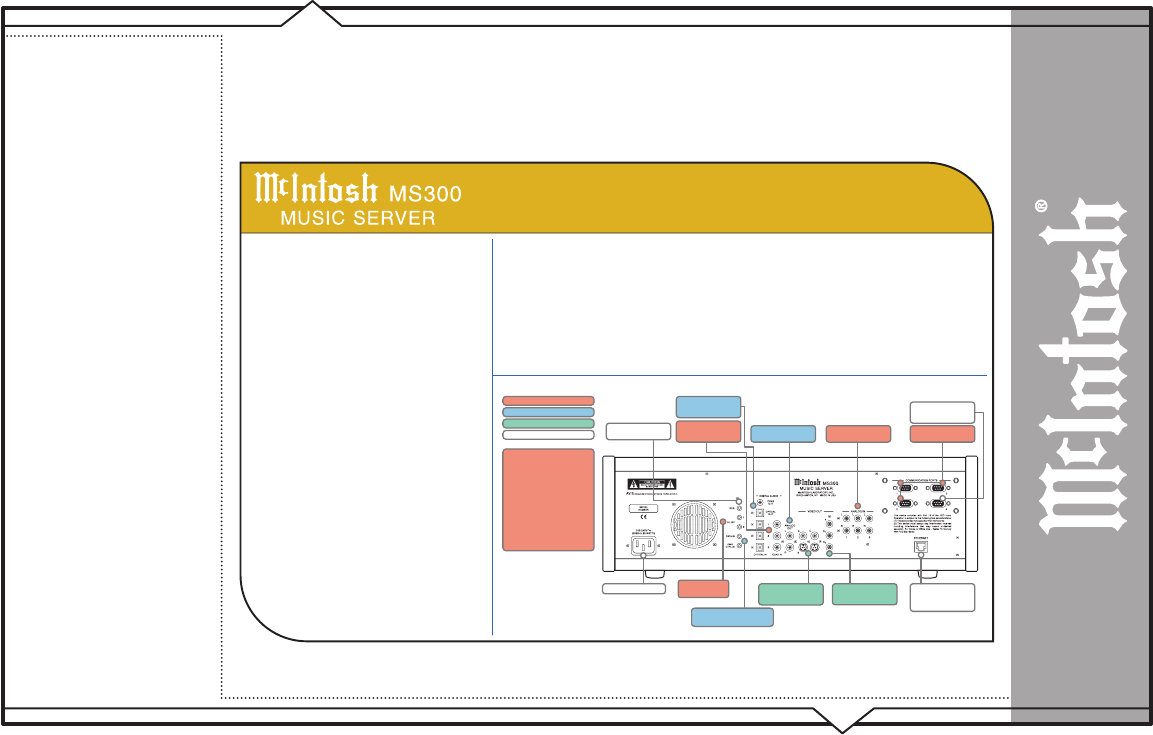
BACK PANEL OVERVIEW
:
Power
to electrical outlet
IR In for IR external
control
S-Link
to control CD
Analog Out to the
receiver for analog audio
Component Video Out
to the TV or other display
device
Ethernet Network Jack
connects the MS300 to
your broadband Ethernet
network.
Coax Out and Optical
Out to the receiver for
digital audio
Optical In and Coax In
from CD changers 1/2/3
for digital audio
RS-232 for external
control, touch screen, or
modem
RS-232 to control CD
changers 1/2/3
Composite or S-Video
Video Out to the TV or
other display device
CHANGER CONNECTION
RECEIVER CONNECTION
DISPLA
Y CONNECTION
GENERAL CONNECTION
Analog audio In from the
CD changers 1/2/3
Quick Setup
SUPPORTED CHANGERS
Sony CD Changers (CDP-CX 200,
300, 400 series with S-Link support)
Sony DVP-CX777ES CD/DVD
Changer
(CDs only)
Pioneer DV-F07 CD/DVD changer
(CDs only)
Kenwood DV-5900M and DV-5050M
DVD/CD Changers
(CDs only)
Locate a stereo RCA audio patch cable.
McIntosh Part No. 040944
changers 1 and 2
Data In / Power Control In
from
McIntosh Preamplifiers/Receivers
SETUP


