


13
RQTV0136
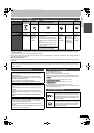
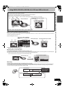
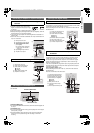
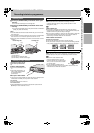
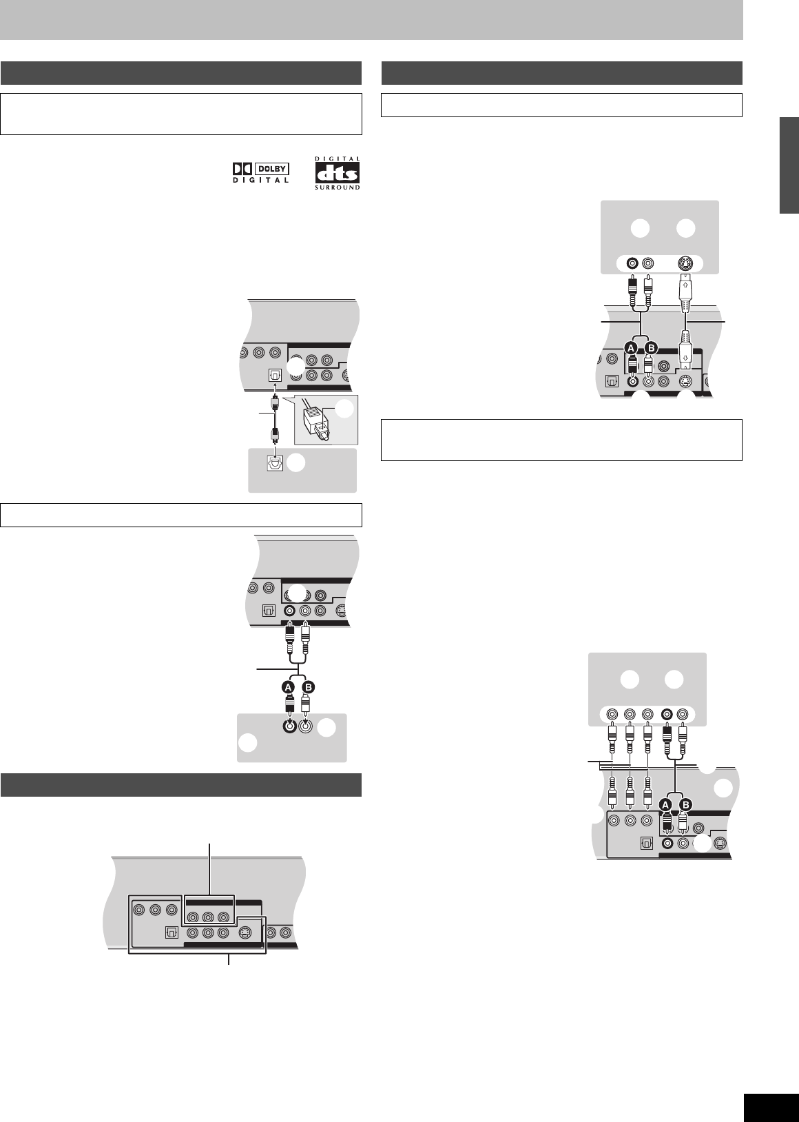
To enjoy multi-channel surround sound on DVD-Video
≥Connect an amplifier with a built-in Dolby
Digital or DTS decoder
displaying the logos
on the right.
≥Change the settings in “Digital Audio Output”. (l 58)
≥Before purchasing an optical digital audio cable (not supplied), check the
terminal shape of the connected equipment.
≥You cannot use any amplifier with a DTS Digital Surround decoder not
suited to DVD.
≥Even if the unit is connected as illustrated, the output of DVD-Audio will
only be in 2 channels.
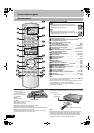
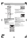
The unit has DVD/VHS COMMON OUT terminals and DVD PRIORITY
OUT terminals.
DVD/VHS COMMON OUT
≥For DVD/VHS COMMON OUT terminals, both DVD and VHS signals can
be output.
DVD PRIORITY OUT
≥This is the dedicated terminal to enjoy pictures played on DVD in higher
picture quality. (l right)
≥The DVD PRIORITY OUT terminals can also output the VHS signal.
However this is not possible during DVD recording or DVD timer
recording.
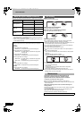
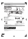
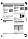
S VIDEO OUT terminal
The S VIDEO OUT terminal achieves a more vivid picture than the VIDEO
OUT terminal. (Actual results depend on the TV.)
After connecting the unit to the TV (l 12), connect the S Video cable as
illustrated below.
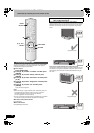
COMPONENT VIDEO OUT terminal
These terminals can be used for either interlace or progressive output
(l 62) and provide a purer picture than the S VIDEO OUT terminal.
Connection using these terminals outputs the colour difference signals
(P
B/PR) and luminance signal (Y) separately in order to achieve high
fidelity in reproducing colours.
If the TV is compatible with progressive output, a high quality picture can
be output because the unit’s component video output terminal outputs a
progressive output signal.
≥For progressive output (l 16)
After connecting the unit to the TV (l 12), connect the video cable as
illustrated below.
≥Connect to terminals of the same colour.
Connecting an amplifier or system component
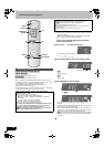
∫ Connecting an amplifier with a digital input
terminal
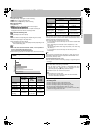
∫ Connection to an analogue stereo amplifier
DVD output and DVD/VHS output
R-AUDIO-L
VIDEO
R-AUDIO-L
VIDEO
S VID
Y
P
B
PR
OPTICAL
MPONENT VIDEO OUT (NTSC: 480p /480i PAL: 576p /576i)
DIGITAL AUDIO OUT
(PCM/BITSTREAM)
DVD/VHS COMMON OUT
DVD PRIORITY OUT
OPTICAL IN
(1)
(3)
(4)
(5)
(2)
A
(1) Rear panel of the unit
(2) Optical digital output terminal
(3) Optical digital audio cable
(not supplied)
Do not bend when connecting.
A Insert fully, with this side
facing up.
(4) Optical digital input terminal
(5) Amplifier’s rear panel
R-AUDIO-L
VIDEO
R-AUDIO-L
VIDEO
S VIDEO
PB
PR
OPTICAL
EO OUT (NTSC: 480p /480i PAL: 576p /576i)
DIGITAL AUDIO OUT
(PCM/BITSTREAM)
DVD/VHS COMMON OUT
DVD PRIORITY OUT
R-AUDIO-L
VIDEO
DVD/VHS COMMON OUT
(2)
(3)
(1)
(4)
RL
AUDIO IN
(5)
(1) Rear panel of the unit
(2) Audio output terminals (L/R)
(3) Audio cable (not supplied)
A Red (R)
B White (L)
(4) Audio input terminals (L/R)
(5) Amplifier’s rear panel
R-AUDIO-L
VIDEO
R-AUDIO-L
VIDEO
S VIDEO
Y
P
B
PR
OPTICAL
COMPONENT VIDEO OUT (NTSC: 480p /480i PAL: 576p /576i)
DIGITAL AUDIO OUT
(PCM/BITSTREAM)
DVD/VHS COMMON OUT
R-AUDIO-L
VIDEO
AV 1
DVD PRIORITY OUT
DVD/VHS COMMON OUT
DVD PRIORITY OUT
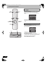
To enjoy even higher fidelity
∫ Connection to the TV’s S Video terminal
∫ Connection to the TV’s component video
terminals
R-AUDIO-L
VIDEO
R-AUDIO-L
VIDEO
S VIDEO
PB
PR
OPTICAL
EO OUT (NTSC: 480p /480i PAL: 576p /576i)
DIGITAL AUDIO OUT
(PCM/BITSTREAM)
DVD/VHS COMMON OUT
R-AUDIO-
DVD PRIORITY OUT
R-AUDIO-L
VIDEO
DVD/VHS COMMON OUT
TV
S VIDEO INS VIDEO IN
(2)
S VIDEO IN
(1)
AUDIO IN
RL
(5)
(3)
(7)
(6)
(4)
(1) Audio input terminals (L/R)
(2) S Video input terminal
(3) Audio cable (not supplied)
A Red (R)
B White (L)
(4) S Video cable (not supplied)
(5) Rear panel of the unit
(6) Audio output terminals (L/R)
(7) S Video output terminal
R-AUDIO-L
VIDEO
R-AUDIO-L
VIDEO
S VIDEO
Y
P
B
PR
OPTICAL
COMPONENT VIDEO OUT (NTSC: 480p /480i PAL: 576p /576i)
DIGITAL AUDIO OUT
(PCM/BITSTREAM)
DVD/VHS COMMON OUT
DVD PRIORITY OUT
(3)
(7)
(5)
(6)
(4)
TV
COMPONENT
VIDEO IN
(1) (2)
AUDIO IN
RL
(1) Component input terminals
(2) Audio input terminals (L/R)
(3) Video cables (not supplied)
(4) Audio cable (not supplied)
A Red (R)
B White (L)
(5) Rear panel of the unit
(6) Component video output
terminals
(7) Audio output terminals (L/R)
STEP 1 Connection
RQTV0136.book 13 ページ 2006年4月19日 水曜日 午後1時28分