


14
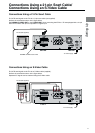
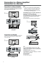
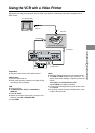
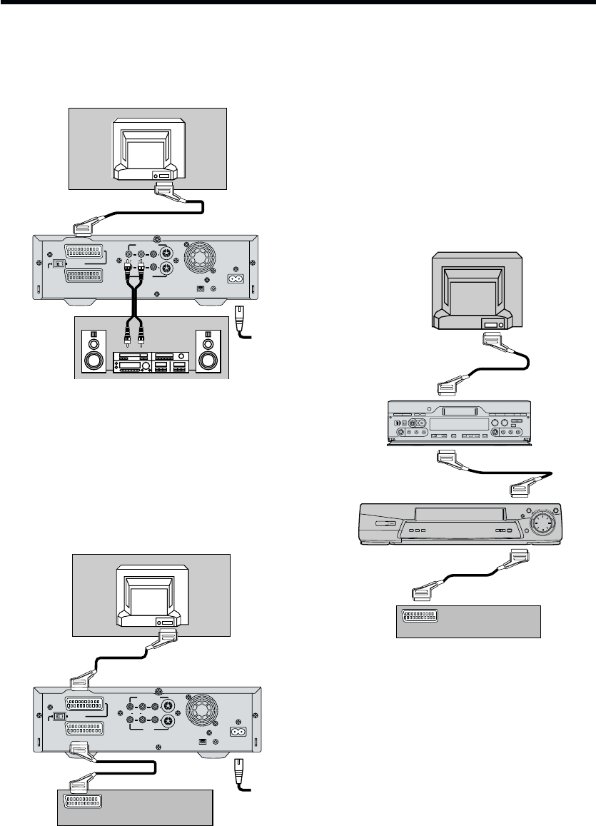
Connection to a Stereo Amplifier
In addition to the connections described on the previous
page, connect the MONITOR OUT (AV3 OUT) sockets
to the Amplifier using an AV cable.
AV1
(
TV
)
AV2
(
EXT
)
MONITOR OUT
R AUDIO L
VIDEO S-VIDEO
DIGITAL STILL
PICTURE OUT
AC INT
SECTEUR
T
¥
DV 1
AV3 IN
S-VIDEO OUT
NORMAL
AV1
(
TV
)
AV2
(
EXT
)
MONITOR OUT
R AUDIO L
VIDEO S-VIDEO
DIGITAL STILL
PICTURE OUT
AC INT
SECTEUR
T
AV3 IN
S-VIDEO OUT
NORMAL
¥
DV 1
Note:
¡ If the TV set is provided with an RGB-compatible
connector, connect the 21-pin Scart cable from the
VCR to this connector. Use the fully-wired 21-pin
Scart cable for connecting the TV set and VCR and
for connecting the VCR and decoder.
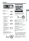
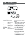
Connections for the “Q Link” Function of
the other TV, VCR and Decoder
The NV-DV2000 does not have the “Q Link” function, but
the connections below link the NV-DV2000 to a TV, a
VCR with tuner and a decoder so that the “Q Link”
function may work.
We recommend this connection for advanced users.
Stereo Amplifier
(Not supplied)
Connection to a Decoder
In addition to the connections described on the previous
page, connect the AV2 socket to the decoder using a
21-pin Scart cable.
Connection to a Stereo Amplifier/
Connection to a Decoder
TV
(Not supplied)
Other VCR (Not supplied)
Decoder (Not supplied)
AV1
AV1
AV2
AV2
Hint:
Turn off the NV-DV2000 so that the “Q Link”, “DATA
LOGIC”, “NEXTVIEWLINK”, “Easy Link”, “Megalogic”,
“SMART LINK” or other logo functions of other TV, VCR
and decoder may work.
The following “Q Link”, “DATA LOGIC”,
“NEXTVIEWLINK”, “Easy Link”, “Megalogic” or “SMART
LINK” functions are available.
≥ Preset Download
≥ Direct TV REC
≥ TV/VCR Auto Power On
Decoder
(Not supplied)
TV
(Not supplied)
TV
(Not supplied)