


9
Before Use
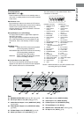
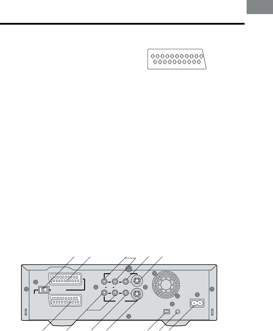
Rear
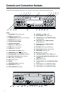
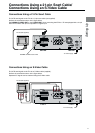
35 NORMAL/S-VIDEO OUT switch for AV1 only [R13]
36 AV1 21-pin Scart socket [AV1 (TV)] [R13,14]
37 Audio Monitor Output sockets [AUDIO OUT (AV3)]
[R13,14,30]
38 Video Monitor Output socket [VIDEO OUT (AV3)]
[R13,30]
39 S-Video Output socket (S-VIDEO OUT) [R13,19]
40 AV2 21-pin Scart socket [AV2 (EXT)] [R14]
The scart terminal is also called “Peritel”, “Euro
Connector” or “Euro AV”.
NORMAL (AV1/AV2) S-VIDEO (AV1)
01 AUDIO OUTPUT 01 AUDIO OUTPUT
CH2 (R) CH2 (R)
02 AUDIO INPUT 02 AUDIO INPUT
CH2 (R) CH2 (R)
03 AUDIO OUTPUT 03 AUDIO OUTPUT
CH1 (L) CH1 (L)
04 AUDIO GND 04 AUDIO GND
05 BLUE GND 05 No connection
06 AUDIO INPUT 06 AUDIO INPUT
CH1 (L) CH1 (L)
07 BLUE 07 No connection
08
SWITCHING VOLTAGE
08 SWITCHING VOLTAGE
09 GREEN GND 09 No connection
10 Connection 10 Connection
(Only when NV-DV2000 is off)
11 GREEN 11 No connection
12 No connection 12 No connection
13 RED GND 13 C OUT GND
14 BLANKING GND 14 No connection
15 RED 15 C OUT
16 BLANKING 16 No connection
17 VIDEO OUTPUT GND 17 Y OUT GND
18 VIDEO INPUT GND 18 VIDEO INPUT GND
19 VIDEO OUTPUT 19 Y OUT
20 VIDEO INPUT 20 VIDEO INPUT
21 GND 21 GND
Caution: RGB reservation for only E/E operation when
connecting the Pay TV decoder.
1 3 5 7 9 11 13 15 17 19
21
2 4 6 8 10 12 14 16 18 20
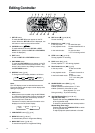
Front (Explanation)
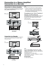
VCR-ON/OFF button (
]]
]]
]/I)
Press to switch the VCR from on to standby mode or
vice versa. In standby mode, the unit is still connected
to the mains.
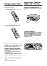
Edit Terminal switch
By connecting a video movie camera or VCR with an
EDIT socket via an Edit cable, various kinds of editing
functions can be performed more quickly and
efficiently between two VCRs or between a VCR and
a video movie camera.
DV Input/Output socket [DV1/DV2(¥)]
To connect the DV cable to digital video equipment
with iEEE 1394-1995.
“¥” is the logo marked on products conforming with
the “i.LINK” specifications. For further details on the
DV terminal, refer to the Glossary of Terms on page
58.
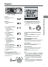
Edit Mode switch
PLAYER: When this VCR is used as the playback
VCR during editing operations.
RECORDER:When this VCR is used as the recording
VCR during editing operations.
≥ Normally set at this position.
PASSIVE: When operating this VCR using another
VCR or an editing controller.
AV1 21-pin Scart socket [AV1 (TV)]
This 21-pin scart terminal carries input and output
signals for both picture and sound. TV sets equipped
with a similar socket can be connected here.
AV1
(
TV
)
AV2
(
EXT
)
MONITOR OUT
R AUDIO L
VIDEO S-VIDEO
DIGITAL STILL
PICTURE OUT
AC INT
SECTEUR
T
¥
DV1
AV3 IN
S-VIDEO OUT
NORMAL
35
36
37
38
39
40
41
42
43
44
46
45
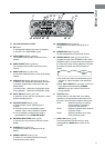
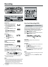
41 Audio Input sockets [AUDIO IN (AV3)]
42 Video Input socket [VIDEO IN (AV3)]
43 S-Video Input socket [S-VIDEO IN (AV3)]
44 DV Input/Output socket [DV1(¥)]
45 DIGITAL STILL PICTURE OUT socket [R20]
46 AC Input socket (AC IN) [R13]