


15
SW position
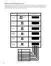
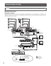
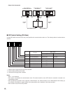
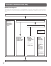
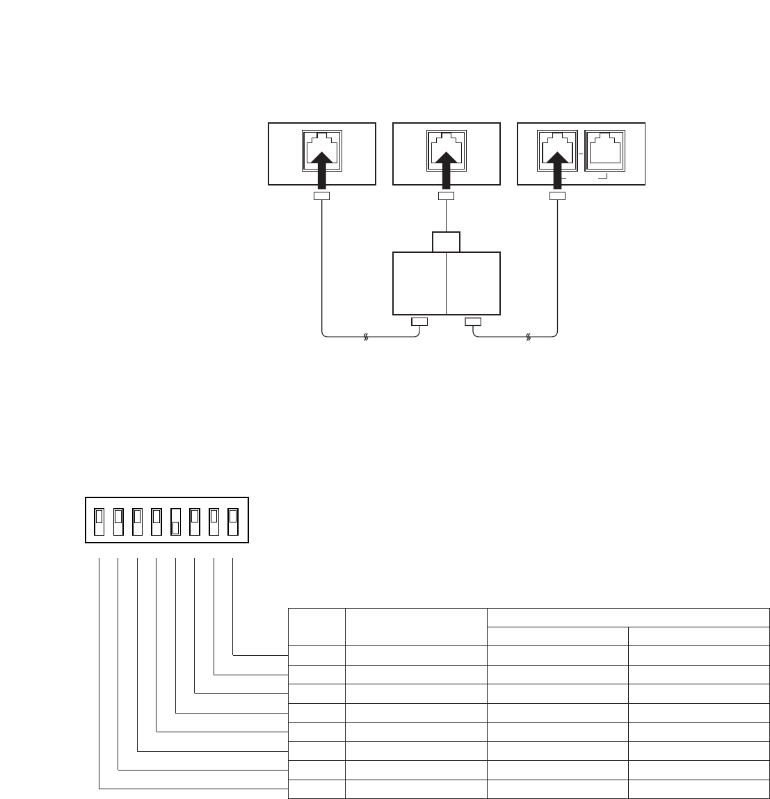
• Daisy Chain Connection
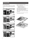
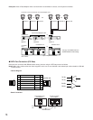
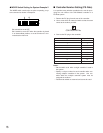
■ DIP Switch Setting (PS
•
Data)
An 8-bit DIP switch mounted on the rear panel specifies the communication mode, etc. The default position is marked with an
asterisk *.
DATA
Data Multiplex Unit
WJ-MP204C
Branch
Cable
Termination:
OFF
Termination:
ON
System Controller
WV-CU360C
DATA DATA
Video Multiplexer
WJ-FS309 (WJ-FS316)
RS-485
Cable
Termination:
ON
RS-485
Cable
MODE
12345678
OFF
ON
OFF
Not used
Function
ON
Bit 6
Bit 7
Bit 8
Bit 5
Bit 4
Bit 3
Bit 2
Bit 1
Operation mode
Baud rate selection
Data transmission mode
Line termination
Reserved
System Unit Version
System Unit Version
System Unit Version
Operator*
Fixed to OFF*
Fixed to OFF*
Off
Fixed to OFF*
Fixed to OFF*
Fixed to OFF*
Fixed to OFF*
Administrator
Not used
Not used
On*
Not used
Not used
Not used
1. Remove the DC plug from the rear of the controller.
2. Set the switch referring to the table.
3. Connect the DC plug to the controller.
Notes:
• Bits 1 - 4 are reserved.
• Bit 5 opens or terminates the communication chain. The switch should be set to OFF when the controller is located in an
intermediate position.
• Bit 6 specifies the operation mode, Operator or Administrator. The switch should be set to Administrator when setting up
the controller. Remember to set this switch to the right position after completion of the setup operation.
• Bits 7 and 8 are used in the OFF position.