


6
MAJOR OPERATING CONTROLS & THEIR FUNCTIONS
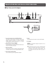
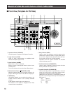
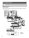
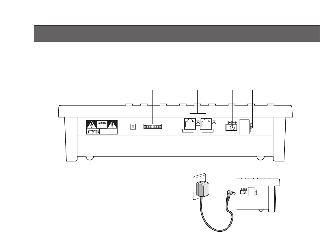
■ Rear View and AC Adapter
DC 9V IN
DATAMODE
RISK OF ELECTRIC
SHOCK. DO NOT OPEN
RISQUE DE CHOCS ELECTROUES
NE PAS OUVRIR
0
9
8
7
6
5
4
3
2
1
r te
CONTROLLER No.
w
q
q Controller Number Switch (CONTROLLER No.)
This switch is used to assign a controller number to the
System Controller to identify it in a system comprising
multiple System Controllers (See page 14). A system
may comprise up to four controllers.
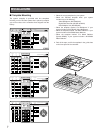
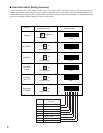
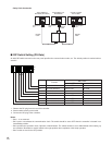
w Mode Selection Switches (MODE)
The DIP switches are used to set communication para-
meters for the System Controller.
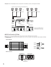
e Data Ports (DATA)
These ports are used to exchange control data with the
connected system units via the supplied RS-485 cable.
r DC 9 V Input Jack (DC 9V IN)
Jack for the DC plug of the supplied AC adapter.
t Clamp
The clamp fastens the power cord to the AC adapter.
y AC Adapter
Caution:
Use only the supplied AC adapter to feed DC 9 V to a
System Controller.
Note: Disconnect the plug from the controller before
setting the controller number switch or mode selec-
tion switch, and reconnect it when finished. The
new settings will take effect when the power is
turned on.
DC 9V IN
y