Mounting the SN10200 to a rack 18
SmartNode 10200 Series User Manual 2 • Hardware Installation
Mounting the SN10200 to a rack
The SN10200 is mounted on a customer provided equipment rack using the mounting hardware packaged in
the box. To rack mount the SN10200, you will need:
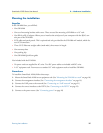
• One 19” customer provided equipment racks. The rack must be solidly anchored to the floor with appro-
priate support at the top of the racks.
• Climate controlled room: 0 to +50 Celsius, 0 to 95% non-condensing humidity.
The SN10200 is housed in a 2U chassis, as described in table 3. It is important that you provide for enough
room on the equipment rack to allow for the installation of the SN10200. Consider the available space on your
equipment rack and the height of the SN10200. Due to the rear-exhaust, heat vents and the efficient heat dis-
sipation design, there is no need to leave any physical vertical space above or below the placement of the
SN10200 on the equipment rack.
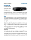
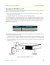
The SN10200 is mounted on the 19” equipment rack using the angle brackets and screws provided in the box.
To mount the SN10200, follow these steps:
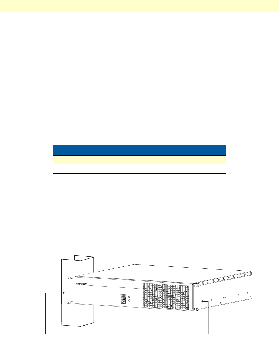
1. Using two metal screws, attach one angle bracket to the front, left-hand side of the SN10200 when viewed
from the front, as shown in figure 2.1 on page 8. Do the same for the angle bracket on the right-hand side.
2. Start mounting equipment at the top-most position of the rack, keeping in mind the space required on the
equipment rack (table 3).
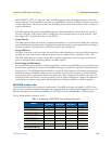
Figure 1. Mounting the SN10200 to a rack
Table 3. SmartNode 10200 Height Requirements
Model Vertical Height
SmartNode 10200 2U (3.5 inches or 89.10 mm)
Patch Panels
a
a. SN10200 models configured with a 32 to 64 T1/E1 TDM mod-
ule require one patch panel for each 32 E1/T1 line grouping.
1U (1.75 inches or 44.45 mm
S
m
art
Nod
e
™
C
o
n
s
o
l
e
E
t
h
e
r
n
e
t
P
o
w
er
T
D
M
+
V
o
I
P
S
m
a
r
t
M
e
d
i
a
G
a
t
e
w
a
y
M
a
n
a
g
e
m
e
n
t
Attach the SmartNode
to the equipment rack
Attach the bracket
to the SmartNode


