Connecting to the PSTN 25
SmartNode 10200 Series User Manual 2 • Hardware Installation
Optical Interface (OC3/STM-1)
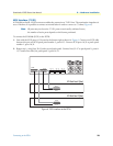
A SN10200-STM-1, with one main and one backup OC3 or STM1 port enables connection to OC3/STM1
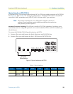
lines (Figure 8). Refer to table 4 for a listing of optical interfaces. The default SFP module for OC3/STM1
connection is SMF, intermediate reach, (SFP-OC3-IR1) 1310 nm with LC type connectors.
Note
Please make certain that the correct SFP model is selected at the time of
ordering. If your installation requires a different model from the one that has
been provided, you must replace it.
Automatic Protection Switching: The APS port is used for OC3/STM1 redundancy. Switchover occurs
automatically based on configurable parameters. It is recommended that APS be used if the installation pro-
vides this feature.
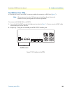
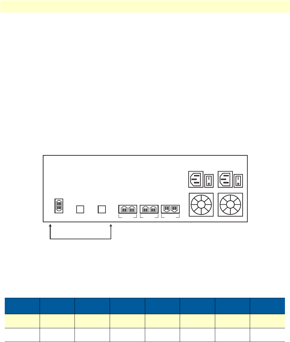
To connect the SN10200-STM1 (Optical Interface) to the PSTN:
1. Connect a fiber optic cable between the Port 0 (Main) port and OC3/STM1 line.
2. Connect a fiber optic cable between the Port 1 (APS) port and OC3/STM1 line.
Figure 8. Optical interface to the PSTN
Table 4. Optical Interfaces
Tranceiver
Model
Description Spec Mode Type
Range
(km)
Wavelength Connection
SFP-OC3-IR1 OC3/STM1 Hot Pluggable Single-mode Intermediate
reach
15 1310 LC
SFP-STM1E STM1
(Electrical)
Hot Pluggable 75 ohms
Copper
Max 180m Variable range N/A DIN (mini-coax)
ETH VoIP SMP
0/0 0/1 0/0 0/1 0/0 0/1
OC3/STM-1
Optical Interface
BIT1
BIT2
APS
MAIN


