


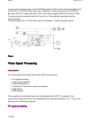
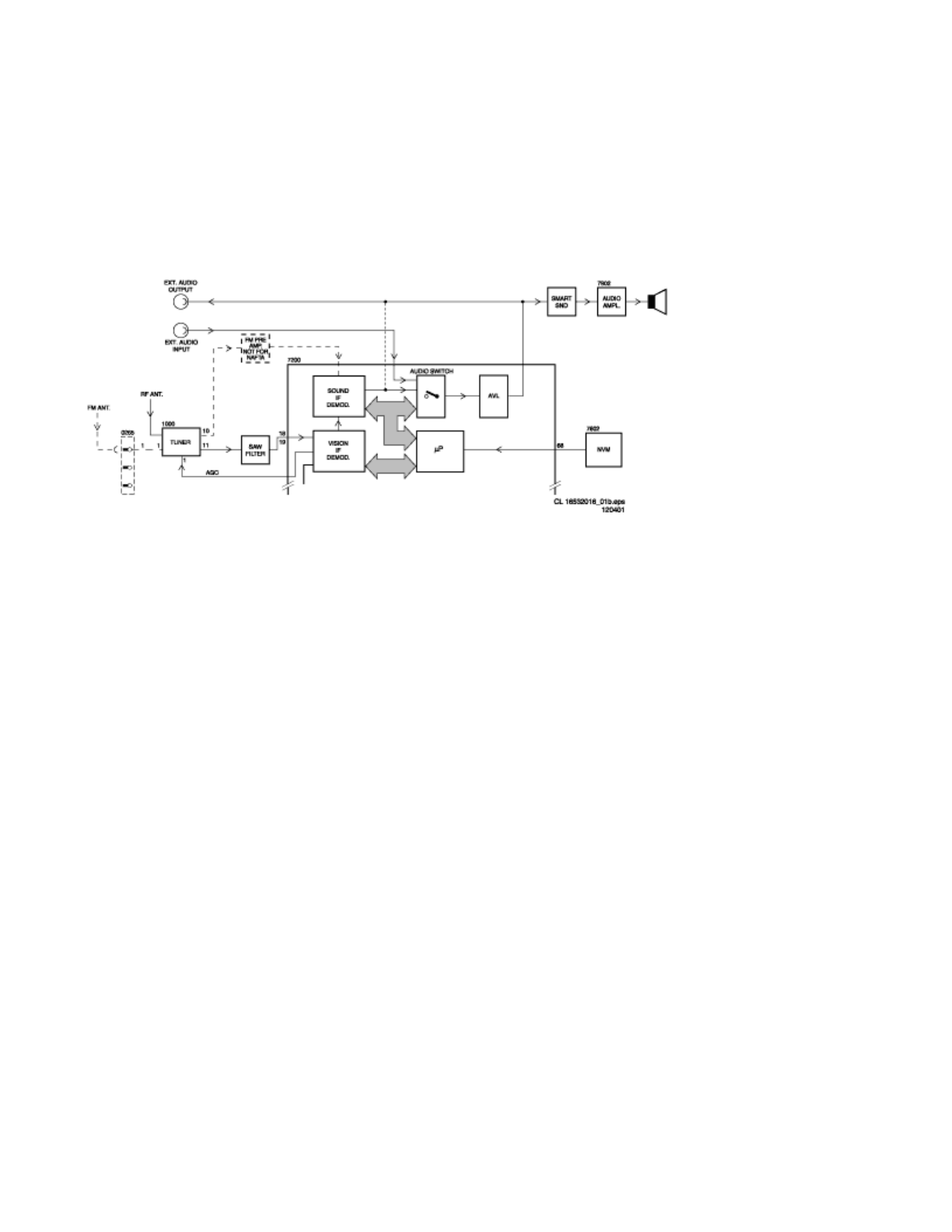
In mono sets, the signal goes via the SAW filter(position 1002), to the audio demodulator part
of the UOC IC 7200.The audio output on pin 48 goes, via the smart sound circuit (7941for
Bass and 7942 for Treble) and buffer 7943, to the audio amplifier(AN7523 at position 7902).
The volume level is controlled at this IC (pin 9) by a ‘VolumeMute’ controlline from the
microprocessor.
The audio signal from IC 7902 is then sent to the speaker / headphoneoutput panel.
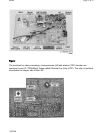
Figure:
Video Signal Processing
Introduction
The video signal-processing path consists ofthe following parts:
z
RF signalprocessing.
z
Video source selection.
z
Video demodulation.
z
Luminance / Chrominance signal processing.
z
RGB control.
z
RGB amplifier
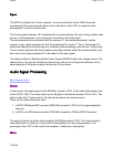
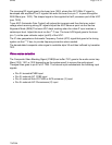
The processing circuits listed above are all integratedin the UOC TV processor. The
surrounding components are for the adaptationof the selected application. The I
2
Cbus is for
defining and controlling the signals.
RF signal processing
Pa
g
e 4 of 32SPMS
7/8/2004