


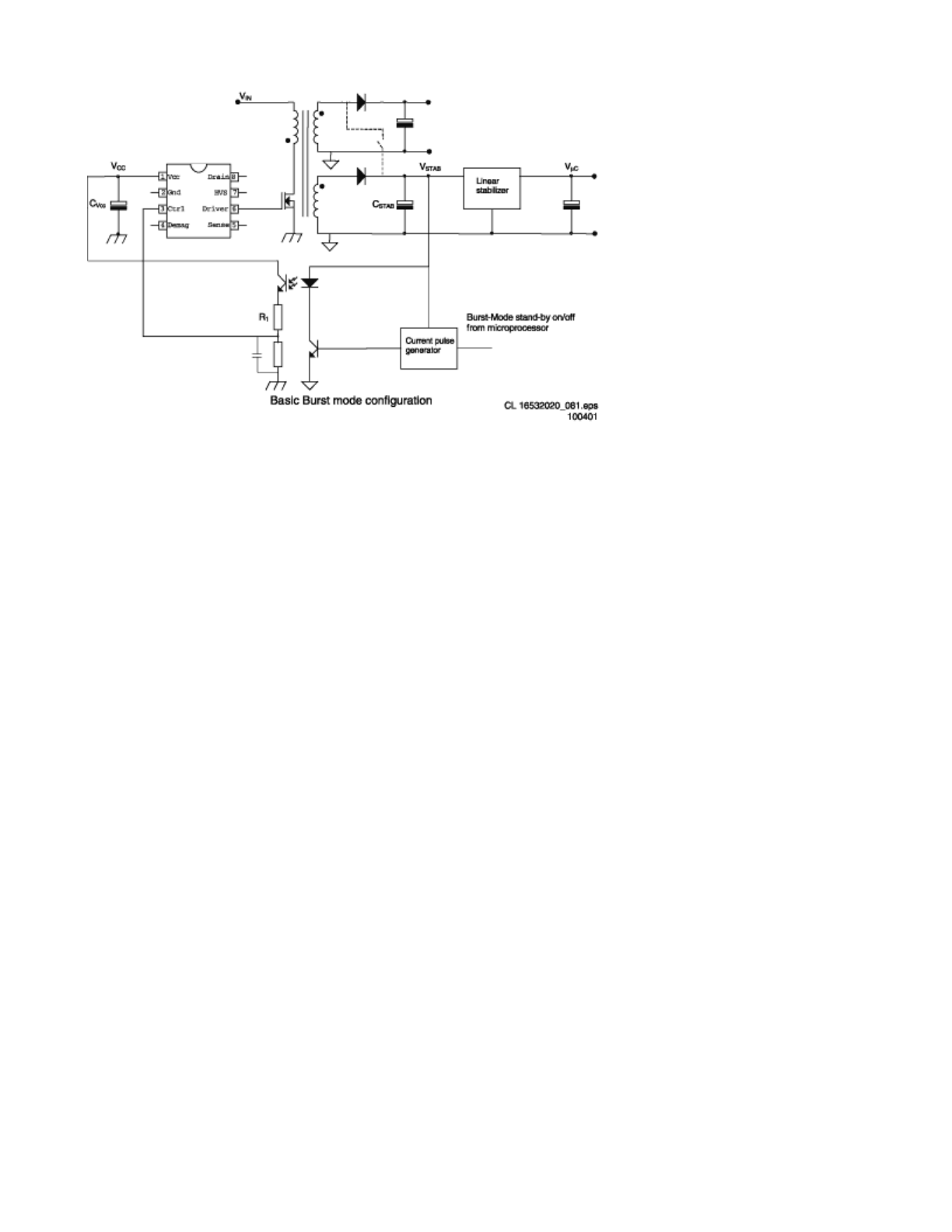
Figure:
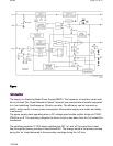
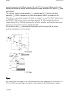
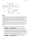
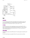
The system enters burst mode standby when the microprocessoractivates the ‘Stdby_con’ line.
Whenthis line is pulled high, the base of Q7541 is allowed to go high.This is triggered by the
current from collector Q7542. When Q7541 turns ‘on’,the opto-coupler (7515) is activated,
sending a large current signalto pin 3 (Ctrl). In response to this signal, the IC stops
switchingand enters a ‘hiccup’ mode. This burst activationsignal should be present for longer
than the ‘burst blank’ period(typically 30 μs): the blanking time prevents false bursttriggering
due to spikes.
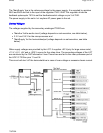
Burst mode standby operation continues until the microcontrollerpulls the ‘Stdby_con’ signal
low again.The base of Q7541 is unable to go high, thus cannot turn ‘on’.This will disable the
burst mode. The system then enters the start-upsequence and begins normal switching
behavior.
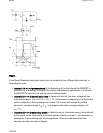
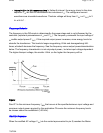
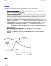
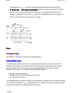
For a more detailed description of one burst cycle, threetime intervals are defined:
z
t1: Discharge of V
CC
when gate drive is active During thefirst interval, energy is
transferred, which result in a ramp-upof the output voltage (V
STAB
)in front of the
stabilizer. When enough energy is stored in thecapacitor, the IC will be switched ‘off’ by
acurrent pulse generated at the secondary side. This pulse is transferredto the primary
side via the opto coupler. The controller will disablethe output driver (safe restart mode)
when the current pulse reachesa threshold level of 16 mA into the Ctrl pin. A resistor R
1
(R3519) is placed inseries with the opto coupler, to limit the current going into theCtrl pin.
Meanwhile the V
CC
capacitoris discharged but has to stay above V
UVLO
.
z
t2: Dischargeof V
CC
when gate drive is inactive During thesecond interval, the V
CC
Pa
g
e 21 of 32SPMS
7/8/2004