


The following additional controls are used:
z
Black current calibration loop Becauseof the 2-point black current stabilization circuit,
both the blacklevel and the amplitude of the RGB output signals depend on the
drivecharacteristics of the picture tube. The system checks whether thereturning
measuring currents meet the requirements, and adapt theoutput level and gain of the
circuit when necessary. After stabilizationof the loop, the RGB drive signals are switched
on. The 2-pointblack level system adapts the drive voltage for each cathode insuch a
way that the two measuring currents have the right value. Thisis done with the
measurement pulses during the frame flyback. Duringthe first frame, three pulses with a
current of 8 μA aregenerated to adjust the cut off voltage. During the second frame,three
pulses with a current of 20 μA are generated to adjustthe ‘white drive’. This has as a
consequence,that a change in the gain of the output stage will be compensatedby a gain
change of the RGB control circuit. Pin 55 (BLKIN) of theUOC is used as the feedback
input from the CRT base panel.
z
Blue stretch Thisfunction increases the color temperature of the bright scenes
(amplitudeswhich exceed a value of 80% of the nominal amplitude).This effect is
obtained by decreasing the small signal gain of thered and green channel signals, which
exceed this 80% level.
z
Beam currentlimiting A beam current limiting circuit inside the UOChandles the contrast
and brightness control for the RGB signals.This prevents the CRT from being overdriven,
which could otherwisecause serious damage in the line output stage. The reference
usedfor this purpose is the DC voltage on pin 54 (BLCIN) of the TV processor.Contrast
and brightness reduction of the RGB output signals is thereforeproportional to the voltage
present on this pin. Contrast reductionstarts when the voltage on pin 54 is lower than 2.8
V. Brightnessreduction starts when the voltage on pin 54 is less than 1.7 V.The voltage
on pin 54 is normally 3.3 V (limiter not active). Duringset switch-off, the black current
control circuit generates a fixedbeam current of 1 mA. This current ensures that the
picture tubecapacitance is discharged. During the switch-off period, the verticaldeflection
is placed in an over-scan position, so that the dischargeis not visible on the screen.
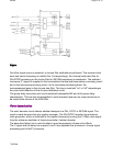
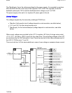
RGB amplifier
From outputs 56, 57 and 58 of IC 7200 the RGBsignals are applied to the integrated output
amplifier (7330) onthe CRT panel. Via the outputs 7, 8 and 9 the picture tube cathodesare
driven.
The supply voltage for the amplifier is +200V and is derived from the line output stage.
Synchronization
Pa
g
e 8 of 32SPMS
7/8/2004