


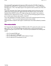
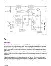

Inside IC 7200 part D the vertical and horizontalsync pulses are separated. These ‘H’ and ‘V’
signalsare synchronised with the incoming CVBS signal. They are then fedto the H- and V-
drive circuits and to the OSD/TXT circuitfor synchronization of the On Screen Display and
Teletext (CC)informationrmation.
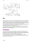
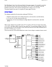
Deflection
Horizontal drive
The horizontal drive signal is obtained froman internal VCO, which is running at twice the line
frequency. Thisfrequency is divided by two, to lock the first control loop to theincoming signal.
When the IC is switched ‘on’, the ‘Hdrive’ signalis suppressed until the frequency is correct.
The ‘Hdrive’ signal is available atpin 30. The ‘Hflybk’ signal is fed to pin 31 tophase lock the
horizontal oscillator, so that Q7462 cannot switch ‘on’ duringthe flyback time.
The ‘EWdrive’ signal for the E/Wcircuit (if present) is available on pin 15, where it drives
transistor7400 to make linearity corrections in the horizontal drive.
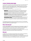
When the set is switched on, the ‘+8V’ voltagegoes to pin 9 of IC 7200. The horizontal drive
starts up in a softstart mode. It starts with a very short T
ON
time of the horizontaloutput
transistor. The T
OFF
ofthe transistor is identical to the time in normal operation. Thestarting
frequency during switch on is therefore about 2 times higherthan the normal value. The ‘on’
time is slowlyincreased to the nominal value in 1175 ms. When the nominal valueis reached,
the PLL is closed in such a way that only very smallphase corrections are necessary.
The ‘EHTinformation’ line on pin 11is intended to be used as a ‘X-ray’ protection.When this
protection is activated (when the voltage exceeds 6 V),the horizontal drive (pin 30) is switched
"off" immediately.If the ‘H-drive’ is stopped, pin 11 will become lowagain. Now the horizontal
drive is again switched on via the slowstart procedure.
The ‘EHTinformation’ line (Aquadag)is also fed back to the UOC IC 7200 pin 54, to adjust the
picturelevel in order to compensate for changes in the beam current.
The ‘filament’ voltage is monitoredfor ‘no voltage’ or ‘excessive voltage’.This voltage is rectified
by diode 6447 and fed to the emitter oftransistor 7443. If this voltage goes above 6.8 V,
transistor 7443will conduct, making the ‘EHT0’ line ‘high’.This will immediately switch off the
horizontal drive (pin 30) viathe slow stop procedure.
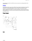
The horizontal drive signal exits IC 7200 at pin 30 andgoes to 7462, the horizontal driver
transistor. The signal is amplified andcoupled to the base circuit of 7460, the horizontal output
transistor.This will drive the line output transformer (LOT) and associatedcircuit. The LOT
provides the extra high voltage (EHT), the VG2voltage and the focus and filament voltages for
Pa
g
e 9 of 32SPMS
7/8/2004