


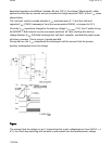
z
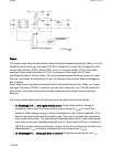
Interval 4:t3 < t < t00 resonance time In thefourth interval, the energy stored in the drain
capacitor C
D
will start to resonatewith the inductance L
P
.The voltage and current
waveforms are sinusoidal waveforms. Thedrain voltage will drop from V
IN
+n•V
OUT
to V
IN
-n•V
OUT
.
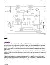
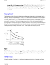
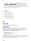
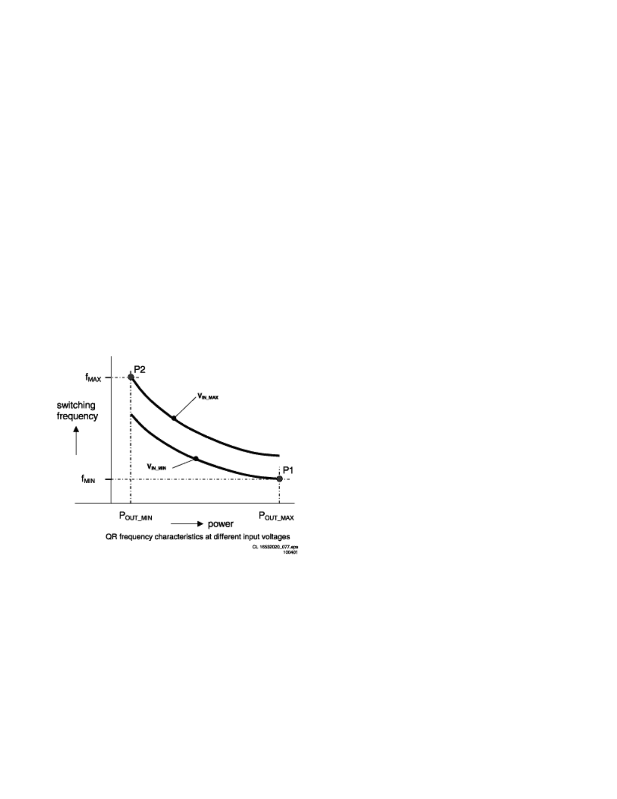
Frequency Behavior
The frequency in the QR-mode is determinedby the power stage and is not influenced by the
controller (important parametersare L
P
and C
D
). The frequency varieswith the input voltage V
IN
andthe output power P
OUT
.If the required output power increases, more energy has to be
storedin the transformer. This leads to longer magnetizing t
PRIM
and demagnetizingt
SEC
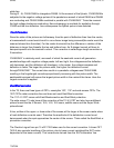
times, whichwill decrease the frequency. See the frequency versus output powercharacteristics
below. The frequency characteristic is not onlyoutput power-, but also input voltage dependent.
The higher theinput voltage, the smaller t
PRIM
,so the higher the frequency will be.
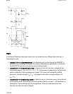
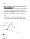
Figure:
Point P1 is the minimum frequency f
MIN
that occurs at the specifiedminimum input voltage and
maximum output power required by the application.Of course the minimum frequency has to
be chosen above the audiblelimit (>20 kHz).
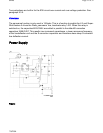
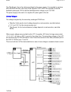
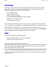
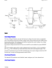
Start-Up Sequence
When the rectified AC voltage V
IN
(via the center tapconnected to pin 8) reaches the Mains
Pa
g
e 17 of 32SPMS
7/8/2004