


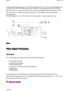
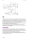

The incoming RF signal goes to the tuner (pos.1000), where the 45.75 MHz IF signal is
developed and amplified.The IF signals then exits the tuner from pin 11 to pass throughthe
SAW filters (pos. 1002). The shaped signal is then applied to theIF processor part of the UOC
(pos. 7200).
Tuner AGC (Automatic Gain Control) will reduce the tunergain and thus the tuner output
voltage when receiving strong RF signals.Adjust the AGC takeover point via the Service
Alignment Mode (SAM).The tuner AGC starts working when the video-IF input reaches a
certaininput level. Adjust this level via the I
2
C bus. The tuner AGCsignal goes to the tuner
(pin 1) via the open collector output (pin22) of the UOC.
The IC also generates an Automatic Frequency Control (AFC) signal that goes to the tuning
system via the I
2
C bus, to provide frequencycorrection when needed.
The demodulated composite video signal is available atpin 38 and then buffered by transistor
7201.
Video source selection
The Composite Video Blanking Signal (CVBS)from buffer 7201 goes to the audio carrier trap
filters (1200, 1201,or 1202 depending on the system used) to remove the audio signal.
Thesignal then goes to pin 40 of IC 7200. The internal input switchselects the following input
signals:
z
Pin 40: terrestrialCVBS input
z
Pin 42: external AV1 CVBS input
z
Pin 44: external Side I/O CVBS or AV2Luminance (Y) input
z
Pin 45: external AV2 Chrominance (C) input
Pa
g
e 5 of 32SPMS
7/8/2004