


Luminance / Chrominance signalprocessing
The output of the YUV separator is fed to theinternal YUV switch, which switches between the
output of the YUV separatoror the external YUV (for DVD or PIP) on pins 51-53. Pin 50 is
theinput for the insertion control signal called ‘FBL-1’. Whenthis signal level becomes higher
than 0.9 V (but less than 3 V),the RGB signals at pins 51, 52 and 53 are inserted into the
pictureby using the internal switches.
Also some picture improvement features are implementedin this part:
z
Black stretch This functioncorrects the black level of incoming signals, which have a
differencebetween the black level and the blanking level. The amount of extension
dependsupon the difference between actual black level and the darkest partof the
incoming video signal level. It is detected by means of aninternal capacitor.
z
White stretch Thisfunction adapts the transfer characteristic of the luminance amplifierin
a non-linear way depending on the average picture content ofthe luminance signal. It
operates in such a way that maximum stretching isobtained when signals with a low
video level are received. For brightpictures, stretching is not active.
z
Dynamic skintone correction This circuit corrects (instantaneouslyand locally) the hue of
those colors which are located in the areain the UV plane that matches the skin tone.
The correction is dependenton the luminance, saturation and distance to the preferred
axis.
The YUV signal is then fed to the color matrix circuit,which converts it to R, G and B signals.
The OSD/TXT signal from the microprocessor ismixed with the main signal at this point, before
being output tothe CRT board (pins 56, 57 and 58).
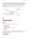
Picture in picture (if present)
The PIP controller M65669FP is an NTSC videoprocessor for TV applications. It contains all of
the analog signalprocessing, control logic and memory, necessary to provide sub-picture
insertionfrom a second, non-synchronized, video source into the main pictureof the TV. This
can be an external source (via the rear I/Oinputs) or the video signal of the tuner.
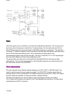
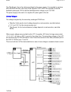
Sync signals are derived from the sandcastle signal and separatedby circuit 7171-7174 on the
PIP-interface, and then fed to pins32 and 33 of the PIP processor 7803.
RGB control
The RGB control circuit enables the pictureparameters contrast, brightness and saturation to
be adjusted, byusing a combination of the user menus and the remote control.
Additionallyautomatic gain control for the RGB signals via cut-off stabilizationis achieved in this
functional block to obtain an accurate biasingof the picture tube. Therefor this block inserts the
cut-off pointmeasuring pulses into the RGB signals during the vertical retraceperiod.
Pa
g
e 7 of 32SPMS
7/8/2004