


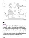

Figure:
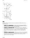
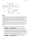
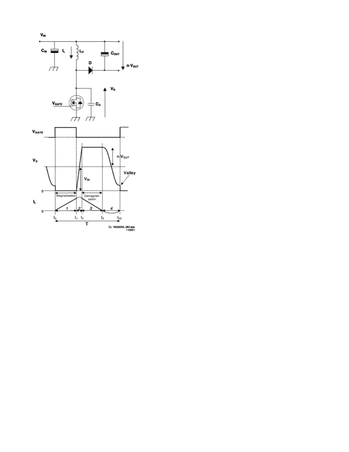
In the Quasi-Resonant mode each period can be dividedinto four different time intervals, in
chronological order:
z
Interval 1: t0 < t < t1primary stroke At the beginning of the first interval,the MOSFET is
switched ‘on’ and energy is storedin the primary inductance (magnetization). At the end,
the MOSFETis switched ‘off’ and the second interval starts.
z
Interval 2:t1 < t < t2 commutation time In thesecond interval, the drain voltage will rise
from almost zero to V
IN
+n•(V
OUT
+V
F
). V
F
is the forward voltagedrop of de diode that
will be omitted from the equations from nowon. The current will change its positive
derivative, correspondingto V
IN
/L
P
, to a negative derivative, correspondingto -n•V
OUT
/L
P
.
z
Interval 3:t2 < t < t3 secondary stroke In thethird interval, the stored energy is transferred
to the output,so the diode starts to conduct and the inductive current I
L
will decrease. In
otherwords, the transformer will be demagnetized. When the inductivecurrent has
become zero the next interval begins.
Pa
g
e 16 of 32SPMS
7/8/2004