


8
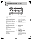
2 NAMES AND FUNCTIONS OF PARTS
INTRODUCTION SETTINGS OTHER OTHER OTHER OTHER
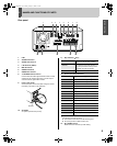
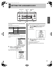
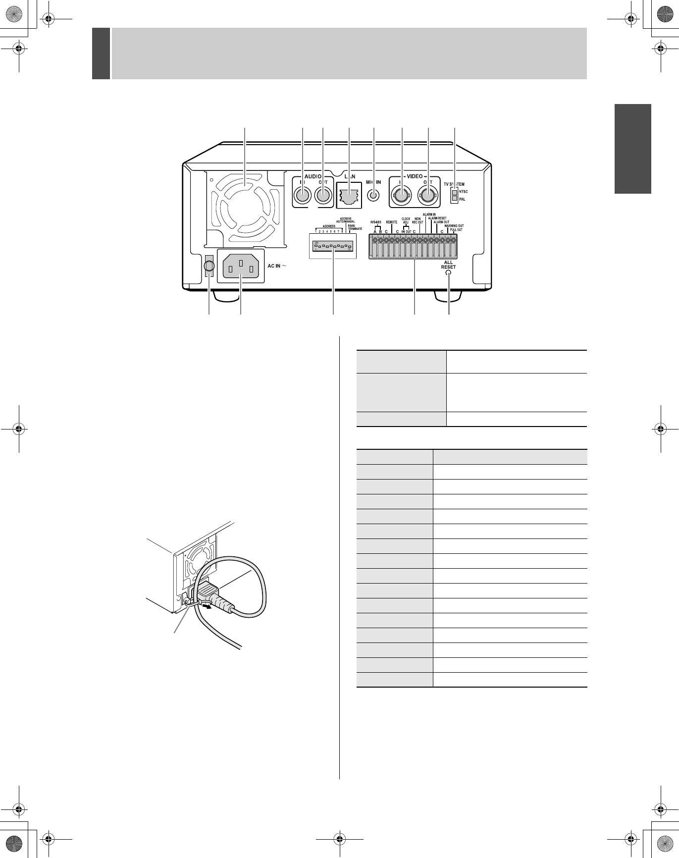
Rear panel
1. FAN
2. AUDIO IN terminal
3. AUDIO OUT terminal
4. LAN terminal (JP.37)
5. MIC IN terminal
6. VIDEO IN terminal
7. VIDEO OUT terminal
8. TV SYSTEM selector switch
Used to select the video signal between NTSC and PAL
systems for the camera input and TV monitor output
connected to the digital video recorder.
9. Power cord holder
Secure the power cord to the holder using the cord tie
(accessory) as shown in the illustration.
10. AC INLET
AC power input terminal (3-core)
11. Dip switches (JP.37)
12. Control and alarm terminals
*
1
Used for twisted-pair cable connection.
*
2
The following warnings are output:
z Hard disk drive error z Fan error z Recording error
z No input signal when VIDEO LOSS is ON.
13. ALL RESET switch
Resets the clock and backup mode setting.
1325678
910 11 12
13
4
Cord tie
ADDRESS
Used to set the device address of the
TCP/IP or RS-485 (SSP) interface.
ADDRESS AUTO
MANUAL
Used to select whether to acquire the
IP address by automatic allocation, or
to specify the lowest-order byte of the
address using the dip switches.
RS485 TERMINATE RS-485 termination ON/OFF switch
Pin Signal
RS485A To RS-485 terminal signal A *
1
RS485B To RS-485 terminal signal B *
1
C Common *
1
REMOTE For wired remote control (VA-RMN01)
C Common
CLOCK ADJ IN Input for clock setting
CLOCK ADJ OUT Output for clock setting
C Common
NON REC OUT NON-REC output
ALARM IN Alarm input
ALARM RESET Alarm reset input
ALARM OUT Alarm output
C Common
WARNING OUT Warning output *
2
FULL OUT Recording area full warning
e_dsr_m800.book Page 8 Friday, January 31, 2003 5:45 PM