4. Remove all cables connected to the ECP.
5. Locate the jumper cover between the “PC” and “SE240” labels on the side of the ECP that
faces the wall.
6. Using a pair of wire cutters, cut through the two tabs on the jumper cover and remove it from
the ECP. Keep the jumper cover in a safe place.
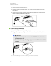
g To remove the USB jumper switch
1. Locate the USB jumper behind the jumper cover port.
2. Using needle-nose pliers, pull the jumper from the two connection posts, and then place it on a
single post.
I I MPORTA NT
o
Only adjust the jumper position. Do not adjust the PC/SE240 switch, which is also
accessible from this area.
o
Do not discard the jumper. Discarding the jumper makes the USB deactivation difficult
to reverse.
3. Insert the USB jumper cover into the USB A port on the front of the ECP.
A PPEND IX C
Disablinguser USBaccess
82


