


Chapter 2 Location and Function of Parts
Chapter 2 Location and Function of Parts 2-5
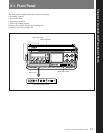
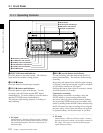
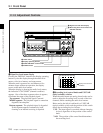
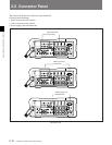
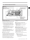
Time indications
This display shows the value selected by the
DISPLAY switch from CTL (control track running
time), time code, or user bits. However, if the REAL
TIME record/set switch (see page 2-9) in the time code
setting controls is in the SET position, the real time
appears here, regardless of the DISPLAY switch
setting.
Tape remaining indication
This shows the length of the remaining tape. Each
segment corresponds to 5 minutes of remaining tape,
but if 30 minutes of tape or more remains, all seven
segments show.
For details of the segment indications and remaining tape
times, see Section 3-2-4 “Checking the Remaining Tape
(page 3-7).
When the remaining tape time is approximately two
minutes, the leftmost segment and the “TAPE”
indication flash, and simultaneously the WARNING
indicator flashes, accompanied by an intermittent
warning tone. At the end of the tape, the WARNING
indicator stays on, and the warning tone becomes
continuous.
Battery capacity remaining indication
This shows the remaining battery capacity. When the
battery pack is fully charged, all seven segments show.
As the battery capacity decreases, the segments
disappear in turn from the right.
For details of the segment indications and remaining battery
capacity, see Section 3-1-4 “Checking the Remaining
Battery Capacity (page 3-4).
When the battery pack is almost exhausted, the
leftmost segment and the “BATT” and “E” indications
flash, and simultaneously the WARNING indicator
flashes, accompanied by an intermittent warning tone.
When the battery pack is completely exhausted, the
WARNING indicator stays on, and the warning tone
becomes continuous.
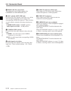
2 WARNING indicator
This lights or flashes when the battery pack is nearly
exhausted, there is less than two minutes of tape left,
or there is a fault in the unit.
For more details, see the section “Warning Indications”
(page A-1).
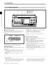
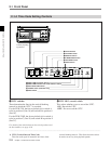
3 RESET button
This resets the time display.
When the CTL value (control track running time) is
displayed, it is reset to “0:00:00:00”. When one of the
time code, or user bit value or real time is displayed, it
is reset to “00:00:00:00”.
4 DISPLAY switch
This selects the time value displayed.
CTL: Displays the tape running time in hours,
minutes, seconds and frames.
TC: Displays a time code.
U-BIT: Displays the user bits.
Note that when the user bits are displayed, no
colons appear.
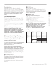
However, the value displayed is not totally determined
by the setting of the DISPLAY switch. The REAL
TIME record/set switch (see page 2-9) takes
precedence, followed by the F-RUN/R-RUN switch
(see page 2-9), and finally the DISPLAY switch
setting.
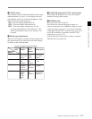
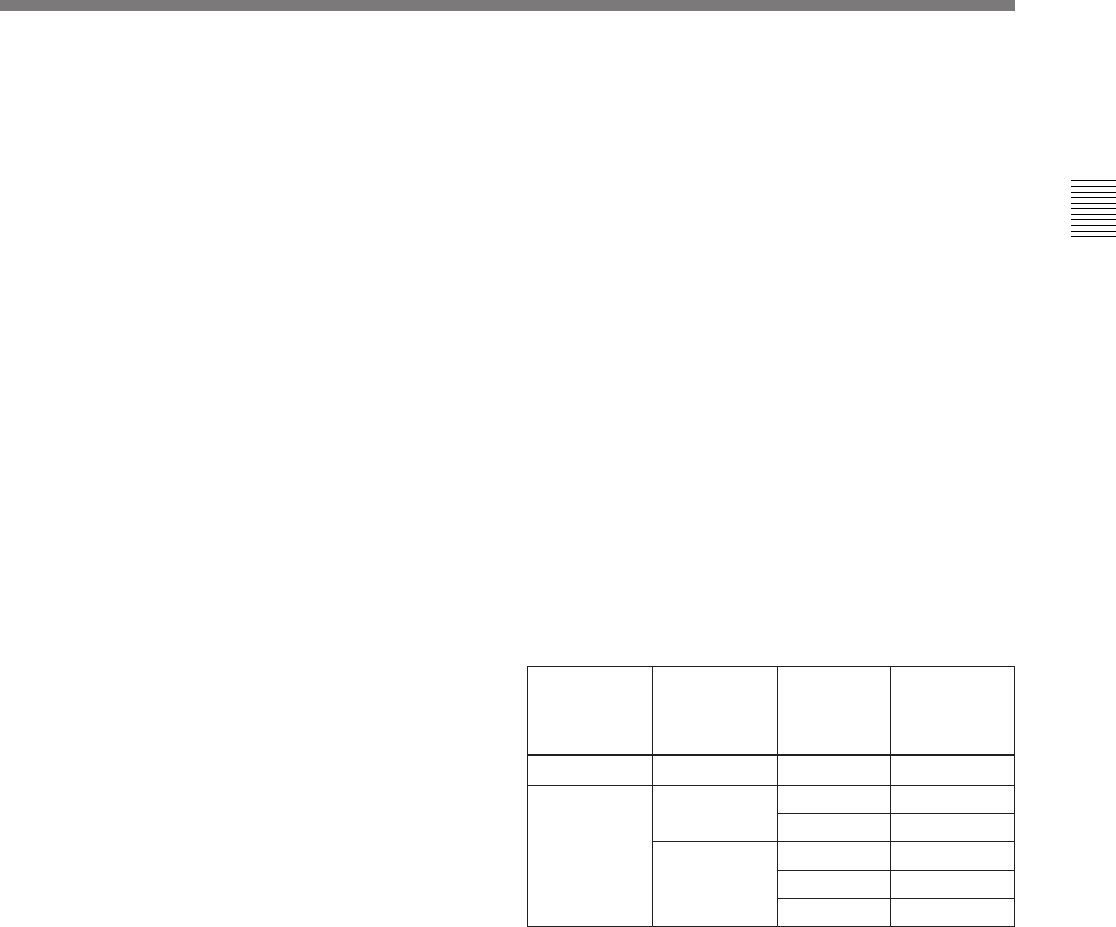
Switch settings and time value displayed
REAL TIME
record/set
switch
position
F-RUN/
R-RUN
switch
position
SET Ignored Ignored Real time
REC ON or
OFF
SET TC or CTL Time code
U-BIT User bits
F-RUN or R-
RUN
CTL CTL
TC Time code
U-BIT User bits
DISPLAY
switch
position
Value
displayed