


Chapter 2 Location and Function of Parts
Chapter 2 Location and Function of Parts 2-13
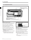
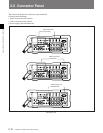
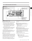
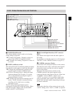
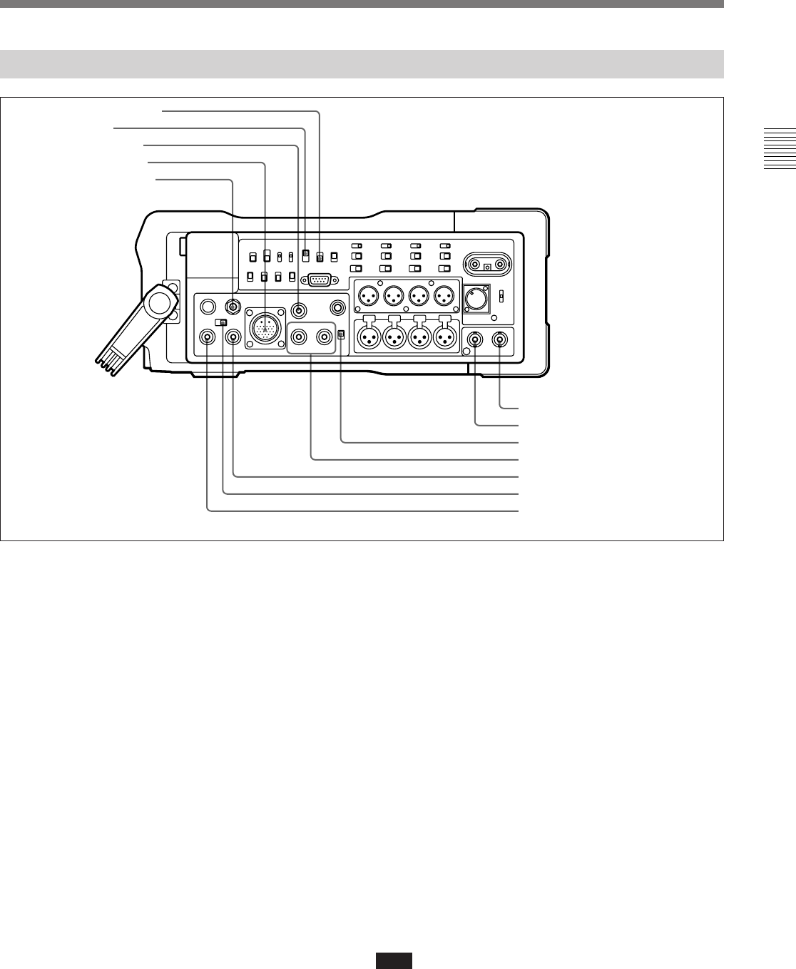
2-2-2 Video Connectors and Controls
Video connectors and controls
1 COLOR FRAME switch
This selects whether or not to enable color framing
during editing or playback.
ON: Enable color framing. Playback is always in
units of four (NTSC) or eight (PAL) fields.
OFF: Disable color framing. Playback is in units of
two fields.
2 CONFI (confidence) switch
This selects the mode for monitoring during recording.
Note that this switch applies to both video and audio.
ON: Monitor the simultaneously playback of the
recorded signals from the confidence heads.
ECC (Error Correcting Codes): Monitor the input
signals unchanged (in E-E mode). If a serious
error is detected while recording the signals, a
warning indication is given.
OFF: Monitor the input signals unchanged (in E-E
mode). The RF envelope is monitored during
recording, and if a fault occurs a warning
indication is given.
The ON setting results in the highest power
consumption, and the OFF setting the lowest. When
using the unit with a battery pack, set the CONFI
switch to the ECC or OFF position.
3 SDI (Serial Digital Interface) OUT connector
(BNC)
This outputs serial digital video and audio signals in
D1 format.
It is possible to switch this output on or off using item
“SDI OUT” in the <VIDEO 2> menu (see page 6-3).
4 CAMERA connector (26-pin)
Connect this to the multi-pin connector on the camera.
This interface carries video, audio and control signals
between the camera and the unit, and also supplies
power to the camera.
When the video input selector switch is in the
CAMERA position, the signals supplied to this
connector form the video input to the unit. When item
“CAMERA” in the <VIDEO 1> menu is set to
“AUTO” (see page 6-3), it is possible to input either
analog component video signals or D1 format serial
digital video and audio signals, depending on the type
of camera connected.
Note
When using other than a Sony camera, do not use the
“AUTO” setting: select “ANA” or “DIGI” as required.
1 COLOR FRAME switch
2 CONFI switch
3 SDI OUT connector
4 CAMERA connector
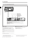
5 VIDEO LEVEL control
6 TC OUT connector
7 TC IN connector
8 SUPERIMPOSE switch
9 VIDEO OUT 1 and 2 connectors
0 SDI IN connector
!¡ Video input selector switch
!™ VIDEO IN connector