


Chapter 2 Location and Function of Parts
Chapter 2 Location and Function of Parts 2-9
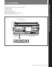
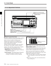
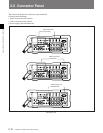
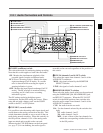
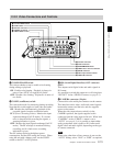
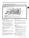
3 DISPLAY switch
This selects which time code is displayed in the status
indication panel (see page 2-4). This switch is only
effective when the DISPLAY switch by the status
indication panel (see page 2-5) is set to the TC or U-
BIT position.
LTC: Display the LTC (Longitudinal Time Code).
VITC: Display the VITC.
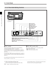
4 F-RUN/R-RUN (free-run/record-run) switch
This selects the operating mode of the internal time
code generator.
F-RUN: The time code generator keeps running,
regardless of the operating state of the unit. Use
this position when setting the time code to real
time or synchronizing it to an external time code.
SET: Move the switch to this position when setting
the time code or user bits value.
R-RUN: The time code generator runs only while
recording. This produces a tape with consecutive
time code values, even when shot intermittently.
5 ADVANCE button
When setting the time code or user bits value,
pressing this button increments the digit which is
flashing.
This button is effective only when the F-RUN/R-
RUN switch or REAL TIME record/set switch is in
the SET position.
6 SHIFT button
When setting the time code or user bits value,
pressing this button cycles through the digits, flashing
the one which can be changed. This button is
effective only when the F-RUN/R-RUN switch or
REAL TIME record/set switch is in the SET position.
7 REAL TIME record/set switch
This selects whether or not to record the real time as
user bit data. It is also used for setting the real time.
REC ON: Record the real time as user bit data.
OFF: Do not record the real time as user bit data.
SET: Set the real time.
8 REAL TIME insertion time code selection
switch
This selects whether to insert the real time as user bit
data in the LTC or VITC.
LTC U-BIT: Insert the user bit value in the LTC.
VITC U-BIT: Insert the user bit value in the VITC.
9 EXT-LOCK/U-BIT switch
This selects whether or not to lock the user bit data to
external user bit data.
ON: The user bit value is locked to the user bit value
inserted in the external time code.
OFF: The user bit value set on this unit is used.
0 DF/NDF switch (DVW-250 only)
This selects whether to use drop frame mode or non-
drop frame mode.
For an explanation of the significance of these modes, see
the footnotes on page 4-9.
DF: drop frame mode
NDF: non-drop frame mode
!¡ DIAG (diagnosis) switch
Press this switch to carry out diagnosis on the unit.
For details, refer to the supplied Maintenance Manual Part
1.