


Chapter 2 Location and Function of Parts
Chapter 2 Location and Function of Parts 2-15
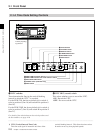
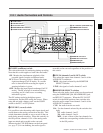
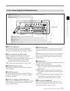
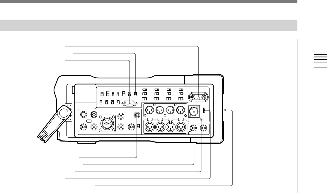
2-2-3 Power Supply and Miscellaneous
Power supply and miscellaneous
1 RFU OUT connector
This outputs video and audio signals and a power
supply to an RF modulator such as an RFU-95UC.
Connect to the input connector of the RF modulator.
2 EXT (external) DC SELECT switch
This selects the way in which the external power
supply (to the DC IN 12V connector) is used.
AUTO: The external power supply is normally used,
but if the voltage drops, the unit switches
automatically to the internal battery pack.
FIX: The external power supply is always used.
3 REMOTE connector (9-pin)
Connect to an external device to remote-control the
unit, as required.
4 DC OUT connector
Connect the DC power cable of the BVR-3 Remote
Controller. This provides a 12 V DC power supply to
the remote controller.
5 DC IN 12V connector (XLR 4-pin, male)
When using an AC-550/550CE AC Adaptor to connect
to an AC power supply, connect the DC cable of the
adaptor to this connector.
6 BREAKER button
If an excess current flows within the unit, the breaker
operates to shut off the power, and this button jumps
out.
Check the internal circuitry of the unit, and check that
there is no persisting fault. Then press in this button.
If the system is able to operate normally, the power
will be restored.
7 MODE switch
This controls the operating mode, making it possible to
control the power consumption.
SAVE: The power consumption is considerably
reduced. Use this mode when operating with a
battery pack.
PB/EE: When the tape is stopped, and while fast
forwarding and rewinding, signals are output in E-
E mode.
PB: Even when the tape is stopped, and during fast
forward and rewind operations, the video and
audio signals recorded on the tape are output.
8 Battery pack compartment
Insert the battery pack (BP-90A or BP-L60). The
battery pack compartment is behind the cover on the
opposite side from the connector panel.
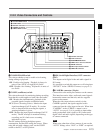
1 RFU OUT connector
2 EXT DC SELECT switch
3 REMOTE connector
4 DC OUT connector
5 DC IN 12V connector
6 BREAKER button
7 MODE switch
8 Battery pack compartment
opposite side